Proteus Design Suite
|
| |
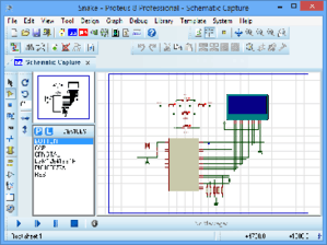 A screenshot of Proteus Design Suite | |
| Developer(s) | Labcenter Electronics Ltd. |
|---|---|
| Initial release | 1988 |
| Stable release |
8.8
|
| Operating system | Windows |
| Type | Electronic design automation |
| Licence | Proprietary |
| Website |
www |
The Proteus Design Suite is a proprietary software tool suite used primarily for electronic design automation. The software is used mainly by electronic design engineers and technicians to create schematics and electronic prints for manufacturing printed circuit boards.
It was developed in Yorkshire, England by Labcenter Electronics Ltd and is available in English, French, Spanish and Chinese languages.
History
The first version of what is now the Proteus Design Suite was called PC-B and was written by the company chairman, John Jameson, for DOS in 1988. Schematic Capture support followed in 1990, with a port to the Windows environment shortly thereafter. Mixed mode SPICE Simulation was first integrated into Proteus in 1996 and microcontroller simulation then arrived in Proteus in 1998. Shape based autorouting was added in 2002 and 2006 saw another major product update with 3D Board Visualisation. More recently, a dedicated IDE for simulation was added in 2011 and MCAD import/export was included in 2015. Support for high speed design was added in 2017. [1]Feature led product releases are typically biannual, while maintenance based service packs are released as required.
Product Modules
The Proteus Design Suite is a Windows application for schematic capture, simulation, and PCB (Printed Circuit Board) layout design. It can be purchased in many configurations, depending on the size of designs being produced and the requirements for microcontroller simulation. All PCB Design products include an autorouter and basic mixed mode SPICE simulation capabilities.
Schematic Capture
Schematic capture in the Proteus Design Suite is used for both the simulation of designs and as the design phase of a PCB layout project. It is therefore a core component and is included with all product configurations.
Microcontroller Simulation
The micro-controller simulation in Proteus works by applying either a hex file or a debug file to the microcontroller part on the schematic. It is then co-simulated along with any analog and digital electronics connected to it. This enables its use in a broad spectrum of project prototyping in areas such as motor control,[2][3] temperature control [4][5] and user interface design.[6] It also finds use in the general hobbyist community[7][8] and, since no hardware is required, is convenient to use as a training[9][10] or teaching tool.[11][12] Support is available for co-simulation of:
- Microchip Technologies PIC10, PIC12, PIC16,PIC18,PIC24,dsPIC33 Microcontrollers.
- Atmel AVR (and Arduino), 8051 and ARM Cortex-M3 Microcontrollers
- NXP 8051, ARM7, ARM Cortex-M0 and ARM Cortex-M3 Microcontrollers.
- Texas Instruments MSP430, PICCOLO DSP and ARM Cortex-M3 Microcontrollers.
- Parallax Basic Stamp, Freescale HC11, 8086 Microcontrollers.
PCB Design
The PCB Layout module is automatically given connectivity information in the form of a netlist from the schematic capture module. It applies this information, together with the user specified design rules and various design automation tools, to assist with error free board design. PCB's of up to 16 copper layers can be produced with design size limited by product configuration.
3D Verification
The 3D Viewer module allows the board under development to be viewed in 3D together with a semi-transparent height plane that represents the boards enclosure. STEP output can then be used to transfer to mechanical CAD software such as Solidworks or Autodesk for accurate mounting and positioning of the board.
See also
References
- ↑ "Length Matching". Labcenter Electronics. Retrieved 13 February 2018.
- ↑ IEEExplore White Paper (May 2011) "Application of Proteus VSM in modelling brushless DC motor drives.".
- ↑ IEEExplore White Paper (Dec 2006)."An efficient approach for implementing Space Vector Modulation for controlling induction motor.".
- ↑ IEEExplore White Paper (Aug 2011)."The simulation of temperature and humidity control system based on Proteus.".
- ↑ IEEExplore White Paper (Aug 2011)."Design of thermostat system based on Proteus simulation software.".
- ↑ IEEExplore White Paper (Dec. 2010)."LED Display Screen Design and Proteus Simulation Based on Single-Chip Microcomputer.".
- ↑ Circuits Gallery (October 2014). "Arduino and Proteus VSM".
- ↑ Elecnote Hobby Projects."Electronic circuits based on PIC microcontrollers and Arduino boards".
- ↑ Online Training with Microchip and Proteus VSM "Get Started with MPLAB® X IDE and Microchip Tools".
- ↑ Future Engineers Proteus VSM projects."Online Training Projects".
- ↑ IEEExplore White Paper (June 2011)."The application of Proteus in teaching of microcomputer principles"
- ↑ IEEExplore White Paper (April 2010)."Application of Proteus virtual system modelling (VSM) in teaching of microcontroller".