Panel switch

The Panel Machine Switching System is an early type of automatic telephone exchange for urban service, introduced in the Bell System in the 1920s. It was developed by Western Electric Labs, the forerunner of Bell Labs, in the U.S., in parallel with the Rotary system at International Western Electric in Belgium before World War I,[1] which was used in Europe. Both systems had many features in common.
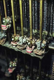
The Panel switch was named for its tall panels which consisted of layered strips of terminals. Between each strip was placed an insulating layer, which kept each metal strip electrically isolated from the ones above and below. Each frame, or "panel" contained 5 such banks of terminal strips. At the bottom, the frame had two electric motors to drive sixty selectors up and down by electromagnetically controlled clutches. The selector was similar in effect to a stepping switch though it moved continuously over the contacts. Each selector had five brushes, each of which could select from 100 terminals arranged in the five groups.
The first Panel-type exchanges were placed in service in Newark, New Jersey,[2] on January 16, 1915 at the Mulberry central office, and on June 12 in the Waverly central office. These system were semi-mechanical systems using telephones at customer stations without a dial.[3] Operators answered calls and keyed the station number into the panel switch. The first fully machine-switching Panel systems using common control principles were placed in service in Omaha, Nebraska in December 1921, followed by the PEnnsylvania exchange in New York City in October 1922.[3][4][5] Most Panel installations were replaced by modern systems during the 1970s and the last Panel switch was decommissioned in the Bigelow central office in Newark by 1983.[6]
Telephone numbering
As in the Strowger (SXS) system, each central office could address up to 10,000 numbered lines, requiring four digits for each subscriber station.
The panel system was designed to interconnect the offices of a city or a local calling area. Each office was assigned a two- (later three) digit office code. Callers dialed the office code followed by the station number. In most situations this led to six-digit (later seven) numbers. But from the beginning the panel system handled seven-digit numbers (later eight), for two reasons. Party line numbers were listed with one of the letters J, M, R, and W following the line number. The caller dialed the office code, the line number, and the digit corresponding to the letter. The panel system was designed to work with manual offices of up to 10,500 lines. To call a line in a manual office, callers dialed the office code followed by the line number, just as they would when calling a number in a fully automatic office. For lines 10,000 and up, callers therefore dialed the office code and a five-digit line number.
Line circuit
As in the divided-multiple telephone switchboard arrangements with which it served until it replaced them, the panel system consisted of an originating section and a terminating section, connected by a line circuit. A subscriber's line had two appearances in a local office, one on the originating side, and one on the terminating side. The line circuit consisted of a line relay on the originating side to indicate that a customer had gone off-hook, and a cutoff relay to keep the line relay from interfering with an established connection. The cutoff relay was controlled by a sleeve lead that, as with the multiple switchboard, could be activated by either the incoming section or the outgoing. The final selector performed a sleeve test to detect a busy line when a subscriber was called.
Supervision (line signaling) was supplied by a District circuit, similar to the plug and light cord circuit that plugged into a line jack on a switchboard. It supervised the calling and called party and, when both had gone on-hook, released the ground on the sleeve lead, thus releasing all selectors, which returned down to their start position to make ready for further traffic. Some District frames were equipped with the more complex supervisory and timing circuits required to generate coin collect and return signals for handling calls from payphones.
Many of the urban and commercial areas where Panel was first used had message rate service rather than flat rate calling. For this reason the line finder had, besides the tip and ring leads for talking and the sleeve lead for control, a fourth wire for the District circuit to send metering pulses to control the message register. The introduction of direct distance dialing (DDD) in the 1950s required the addition of automatic number identification equipment for centralized automatic message accounting.
The incoming section of the office, being fixed to the structure of the last four digits of the telephone number, had a limit of 10,000 phone numbers. In some of the urban areas where Panel was used, even a single square mile might have three or five times that many. Thus the incoming selectors of several separate switching entities shared floor space and staff, but required separate incoming trunk groups from distant offices. Sometimes an Office Select Tandem was used to distribute incoming traffic among the offices. This was a Panel office with no senders or other common control equipment; just one stage of selectors and accepting only the Office Brush and Office Group parameters. Panel Sender Tandems were also used when their greater capabilities were worth their additional cost.
Outgoing calls
The various switching entities in the building could share the same outgoing section, and this was particularly advantageous for trunks to particularly distant parts of the city, consolidating traffic that would otherwise be scattered among smaller and less efficient trunk groups or require using a tandem switch office.
Idle outgoing trunks were picked by the traditional "sleeve test" method, as lines were, except that hunting was the usual practice for trunks rather than a special service feature. The selector moved upward to the proper trunk group, and then through twenty terminals, checking for one with an un-grounded sleeve lead, then selecting and grounding it. If all the trunks were busy, the selector sent back an All Circuits Busy tone (reorder tone). There was no provision for alternate routing as in earlier manual systems and later more sophisticated mechanical ones.
Sender
While the Strowger (step-by-step) switch moved under direct control of dial pulses that came from the telephone dial, the more sophisticated Panel switch had senders, which registered and stored the digits that the customer dialed, and then translated the received digits into numbers appropriate to drive the selectors to their desired position: District Brush, District Group, Office Brush, Office Group, Incoming Brush, Incoming Group, Final Brush, Final Tens, Final Units.
Once the first two or three digits of the call were registered, the sender called in a decoder, which took the digits as input, and returned as output District and Office brush and group settings. The sender then registered these settings, and used them to direct the selectors to the proper outgoing trunk to route the call. The decoder also determined the proper rate at which to operate the message register and gave this information to the sender, which set this rate for the call.
District and Office parameters were variable translations supplied by the decoder, while Incoming parameters and Final Brush were a fixed translation from the Thousands and Hundreds digits of the phone number, merely to adapt efficiently to the capabilities of the Panel selector.
When the sender's job was complete, it connected the talk path from the originating to the terminating side, and dropped out of the call, thus being idle for accepting the next caller. A comparatively small number of senders could handle a large amount of traffic, as each was only used for a short duration during call setup. This principle became known as common control, and was used in all subsequent switching systems.
Fault detection in sender
Revertive pulsing (RP) worked faster than standard dial pulses, but the main advantage was in problem detection. In earlier systems, when a worn pawl or other problem in a Strowger selector caused it to fail to advance, only the calling party could detect the error as no connection was achieved. The caller eventually lost patience and redialed the call. The same user or another might get connected to the faulty selector again. Therefore, one bad Strowger selector could block many calls until subscriber complaints alerted staff to the problem.
In revertive pulsing, the pulses were sent in the reverse direction to the sender, a complex and sophisticated piece of hardware. If a selector failed to advance, it stopped sending pulses to the sender. A timer in the sender detected the failure, returned a trouble tone to the caller, held the switch train out of service with a grounded sleeve lead so no other caller could use the faulty circuit. An automated alarm alerted maintenance staff.
Interoffice signaling
Calls between two panel offices, or calls within a single office, used revertive pulsing for signaling. The originating office inserted a compensating resistance during pulsing so its loop relay encountered the same resistance for all trunks.[7]
Revertive pulsing is a method of signaling in which the terminating equipment sends pulses backwards to the originating equipment as it hunts for the appropriate terminal. This is in contrast to more modern forms of forward pulsing where the originating equipment will directly outpulse to the terminating side the information it needs to connect the call. In Panel offices, as the selectors were driven upwards by the motors, brushes attached to the vertical selector rods wiped over commutators at the top of the frame. These commutators contained alternating segments which serve either as insulators or conductors. When the brush passed over a conductive segment, it was grounded, thereby generating a pulse which was sent back to the sender in the originating office for counting. When the sender counted the appropriate number of pulses, it cut the power to the solenoid in the terminating office, and caused the brush to stop at its current position.
Later systems maintained compatibility with revertive pulsing, even as more advanced signaling methods were developed. The Number One Crossbar, which was the first successor to the Panel system also used this method of signaling exclusively, until later upgrades introduced newer signaling such as Multi-frequency signaling.
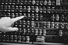
For compatibility with manual offices, two types of signaling were supported. In areas with mostly machine switches and a few manual switchboards, Panel Call Indicator (PCI) signaling lit lamps on the B operator's desk at the terminating manual office. The lamps illuminated digits on a display panel corresponding to the number dialed. The manual operator connected the call to the appropriate jack, and then repeated the process for the next incoming call. In areas with mostly manual switches, the Call Annunciator signaling system was used to avoid installing lamp panels at every operator station. The Call Annunciator used speech recorded on strips of photographic film to verbally announce the called number to the answering operator.
PCI continued in use for tandem purposes, decades after its original need had disappeared. In the 1950s auxiliary senders were added for storing more than eight digits, and sending by multi-frequency (MF) signaling for direct distance dialing (DDD).
Compatibility with manual offices
Panel was installed in cities where many stations still used manual (non-dial) service. Calls from panel offices to manual offices required PCI (Panel Call Indicator) signals to tell the "B Board Machine Incoming" operator or incoming operator the phone number. The called number appeared on a lit display, enabling the operator to complete the call by plugging in the appropriate jack, and ringing the subscriber.
Calls from manual offices to panel offices required the A board, or outgoing operator, to request the number from the caller, connect to an idle trunk to the distant exchange and relay the desired number to the B Board Manual Incoming Call operator, who keyed it to the Panel machine for setting up the incoming and final frames to the called telephone number.
Motor power
The panel switch is an example of a power drive system, in that it used 1/16 horsepower motors to drive the selectors vertically to hunt for the desired connection, and back down again when the call was completed. In contrast, Strowger or crossbar systems used individual electromagnets for operation, and in their case the power available from an electromagnet limits the maximum size of the switch element it can move. With Panel having no such restriction, its dimensions were determined solely by the needs of the switch, and the design of the exchange. The driving electric motor can be made as large as is necessary to move the switch elements. Thus, most calls required only about half as many stages as in earlier systems. Motors used on panel frames were capable of operating on alternating (AC) or direct current (DC), however they could only be started with DC. In the event of an AC power failure the motor would switch to its DC windings, and continue running until AC power was restored.
Upgrades

Throughout its service time, the Panel system was upgraded as new features became available or necessary. Starting in the mid-1920s, such upgrades improved the initial design. Major attention was initially focused on improving the sender. Early two- and three-digit type senders stored dialed digits on rotary selector switches. The senders employed translators to convert the dialed digits into the appropriate brush and group selections needed to complete the call. As better technology became available, Panel senders were upgraded to the all-relay type. These were more reliable, and in addition, replaced the translator equipment with decoders, which also operated entirely with relays, rather than with motor-driven apparatus, which yielded faster call completion.
Another important improvement involved a fundamental change in the electrical logic of the switching system. The Panel originally shipped in a ground cut-off (GCO) configuration. A busy line condition was indicated by ground potential at the cut-off relay, and thus at the sleeve lead, which would be detected by the selector as it hunted over the terminals. Starting in 1929, all newer panel systems were deployed as battery cut-off (BCO) systems.[8] In this revision, the presence of –48Vbattery level on the sleeve lead indicated busy status. This change necessitated a fundamental change in the design of the system, and was undertaken for many reasons. One of the most notable was that GCO offices were more prone to fire.[9]
The line finder was also improved during the system's lifetime. Originally, the line finder frame had a capacity of 300 lines each, and used 15 brushes (vertical hunting segments) on each rod. This was intended to reduce hunting time as there were more brushes hunting over a shorter distance. As these line finders went into service, however, it became evident that 15 brushes on each vertical selector rod were quite heavy, and needed springs and pulleys at the top of the frame to compensate for their mass. Later line finders used 10 brushes and rearranged the layout to accommodate 400 lines per line finder frame. This increased capacity while eliminating the need for compensating equipment.
Western Electric estimated that the design changes of 1925 to 1927 accounted for a 60% reduction in overall costs for the Panel system.[9]
The following table presents early major panel system upgrades:[10]
| Year | Line finder type | Sender connection type | Maximum number of senders per group |
Sender type | Cut-off relay type |
|---|---|---|---|---|---|
| 1920 | Line Switch (200-type) | Sender Selector | 22 | Translator | GCO |
| 1920 | 300 pt line finder | Sender Selector | 22 | Translator | GCO |
| 1924 | 400 pt line finder | Sender Selector | 22 | Translator | GCO |
| 1926 | 400 pt line finder | Rotary Link | 44 | Translator | GCO |
| 1927 | 400 pt line finder | Panel Link | 100 | Translator | GCO |
| 1928 | 400 pt line finder | Panel Link | 100 | Decoder | GCO |
| 1929 | 400 pt line finder | Panel Link | 100 | Decoder | BCO |
References
- ↑ Fagen, M.D.; Amos, E.Joel; Schindler, G. E. (1975). A History of Engineering and Science in the Bell System: Switching Technology. Bell Telephone Laboratories. pp. 581, 607. ISBN 9780932764027.
- ↑ Fagen, M.D.; Amos, E.Joel; Schindler, G. E. (1975). A History of Engineering and Science in the Bell System: Switching Technology. Bell Telephone Laboratories. p. 571. ISBN 9780932764027.
- 1 2 B. Gherardi, H.P. Charlesworth, Machine Switching for the Bell System, Bell Telephone News 9 (9), p14 (April 1920)
- ↑ Bell Laboratory Record 30(1) p.12, Historic Firsts: Lettered Dial (January 1950)
- ↑ Sheldon Hochheiser (IEEE History Center) http://ethw.org/Electromechanical_Telephone-Switching
- ↑ Western Electric, The Last Panel Office, WE Magazine 1983 No. 1 p.22
- ↑ Revertive Pulsing Patent #US3875346 A, 1975
- ↑ Fagen, M.D.; Amos, E. Joel; Schindler, G.E. (1975). A History of Engineering and Science in the Bell System: Switching Design. Bell Telephone Laboratories. p. 19. ISBN 9780932764027.
- 1 2 Fagen, M.D.; Amos, E. Joel; Schindler, G.E. (1975). A History of Science and Engineering in the Bell System: Switching Technology. Bell Telephone Laboratories. p. 18. ISBN 9780932764027.
- ↑ The Panel Dial System Traffic Layouts. Western Electric Company, Inc. 1937. p. 2.
External links
- Call switching by panel switch at the Seattle Museum of Communications.
- Archive Footage of early panel system.
- Survey of telephone switching
- A panel final selector frame at the Museum of Communications.
- Phone Trips: 1970s-era recordings of telephone calls involving panel switches by Evan Doorbell.
- MP3 recording of revertive pulsing, followed by machine ringing and the clicks of the Panel test line.