PDP-14
The PDP-14 was a specialized computer from Digital Equipment Corporation. Unlike DEC's general-purpose computers, which are simply called computers, this unit had no data memory or data registers and was intended as an industrial controller - a Programmable logic controller (PLC).
Its instructions can test Boolean input signals, set or clear Boolean output signals, jump conditional or unconditionally, or call a subroutine.
I/O is line voltage.
Later versions (for example, the PDP-14/30, whose instruction set was not binary compatible)[1] are based on PDP-8 physical packaging technology. There also was a PDP-14/35[2] and a lower cost/reduced I/O capability PDP-14/L.
Hardware
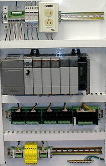
The 12-bit PDP-14 could hold a maximum of 4K words for instructions. The system's configuration included a control unit and a number of external boxes:[1]
- I-boxes (BX14) were for discrete inputs from the controlled system. Up to 256 input sources could be addressed.
- O-boxes (BY14) could control up to 255 actuators in the controlled system.
- A-boxes could be filled with timer modules for controlling time-driven events or retentive storage modules which were not cleared with power loss. A-boxes occupied the output address space along with the O-boxes.
- S-boxes were essentially the same as the O-boxes, but there was no real output device. This enabled storing intermediate results. S-boxes also used the shared output address space.
Hence the combined usable output address space of the O-boxes, A-boxes and S-boxes was 255 or fewer.
Registers
The PDP-14 has seven 12-bit registers:
- IR
- PC1 & PC2
- MB
- SPARE
- INPUT and OUTPUT.
Instructions
Among the PDP-14 instruction were:[1]
- TRR - to move data between some (but not all) of the registers - TRansfer Register (contents).
- PC1 and SPARE have increment and decrement capabilities, permitting TRR to modify the value loaded into the register.
- JMS - JuMp to Subroutine - at the address specified in the following 12-bit word.
- JMR - JuMp to RETURN from a subroutine, to ADDRESS+1 of the most recent JMS.
In effect, JMR is actually a specific TRR in which PC2 is transferred to PC1.
- SKP - SKiP - is a TRR in which PC1 is incremented by 1.
There were also TEST instructions (Test if something is ON or OFF) and SET instructions (SYN - Set "Y" oN, SYF - Set "Y" ofF).
Software
The original PDP-14 required that programming be done by DEC.[4]
Subsequently,[4] software development for the PDP-14 was done on another system, the PDP-8. A PDP-8 program named SIM-14 allowed for simulating the PDP-14.
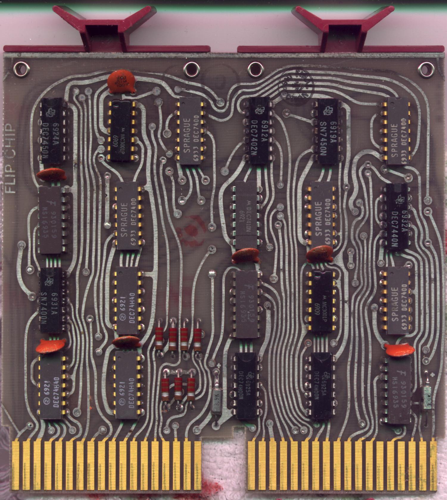
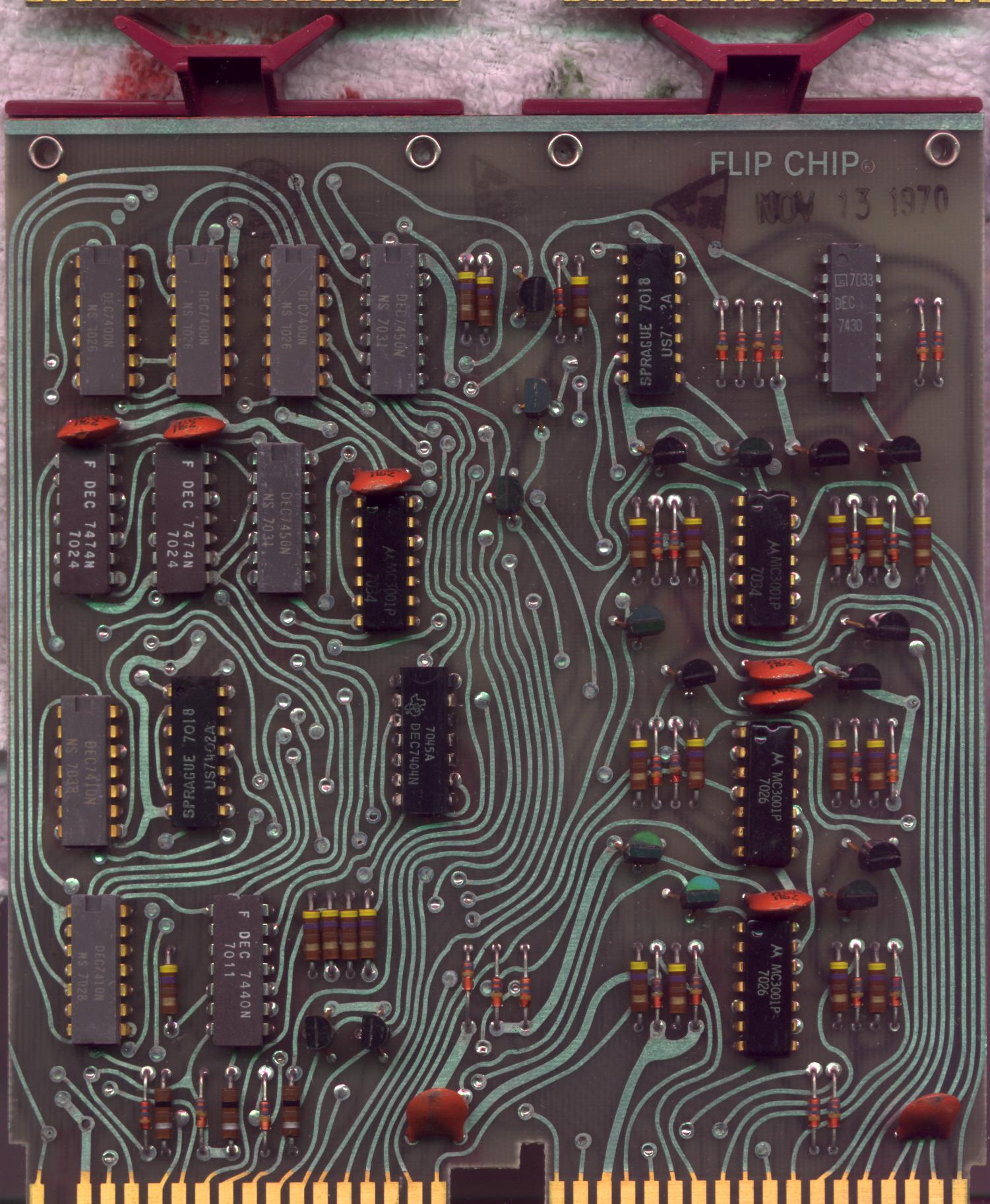
Photos
See also
References
- 1 2 3 4 "DEC PDP-14 Industrial Controller".
- ↑ DIGITAL EQUIPMENT CORPORATION - Nineteen Fifty-Seven To The Present (PDF). Digital Equipment Corporation. 1975.
- ↑ of size ONE: PC2 !
- 1 2 Randall Brodzik (August 27, 2014). "Inside the competition for the first PLC".