Linesman/Mediator
Linesman/Mediator was a dual-purpose civil and military radar network in the United Kingdom between the 1960s and 1984. The military side (Linesman) was replaced by the Integrated United Kingdom Air Defence Ground Environment System (IUKADGES), while the civilian side (Mediator) became the modern public-private National Air Traffic Services (NATS).
In the 1950s, the Royal Air Force was installing a new radar network known as ROTOR using the advanced AMES Type 80 radars organized into a small number of Master Control Centres. These Centres centralized and greatly simplified the task of intercepting aircraft across the entire UK airspace. While these installations were in progress, in the early 1950s CSF introduced the carcinotron, which could output a radio signal at any desired frequency. This made it a very effective jamming system, and it appeared it could render ground-based radars like ROTOR's useless.
Considering several possible solutions, the RAF selected an experimental radar known as Blue Yeoman, but later known as the AMES Type 85. This radar changed its frequency with every pulse, making it impossible for the carcinotron to know what frequency to jam. A second system, AMES Type 84, aimed to simply overpower jamming. Additionally, the "Winkle" system would look for carcinotron broadcasts and track them passively with the same accuracy as the radars. The RAF initially proposed an extensive network of these systems similar to ROTOR, but as part of the 1957 Defence White Paper the threat was seen to be moving from bombers to missiles, and in late 1958 a much smaller system with only five radars and a single control centre became "Plan Ahead".
During this same period, civilian air traffic was increasing dramatically, and led to the 1962 formation of the National Air Traffic Control Services organization to handle national-scale air traffic control (ATC). The Plan Ahead concept of sending data from multiple radar sites to a single control centre had obvious benefits for the ATC role, and led to plans to share data between the military and civilian sides. Plan Ahead became Linesman and Mediator, respectively. The systems were to share locations in West Drayton, just north of Heathrow and Prestwick near Glasgow, while Mediator planned a third site in Preston in Lancashire. Ultimately all three Mediator sites were built, while only the temporary "L1" at West Drayton was ever completed as part of Linesman.
History and plan
Linesman, whilst part of the "Ahead" plan, evolved out of the study into combining radar information carried out in the late 1950s by the Royal Radar Establishment (RRE) at Malvern with the participation of the Automatic Telephone and Electric Company (ATE) of Liverpool. The concept was to reduce the complexity of the existing distributed ROTOR system using multiple Master Radar Stations (MRS) with a single site designated "L1" (Linesman 1). L1 would be able to direct all of the air command using a complete air picture of the UK.
During the initial stages of the project RRE became the Royal Signals and Radar Establishment (RSRE) and, in 1962, AT&E was merged with Plessey.
Linesman was a comprehensive upgrade of the UK air defence system; along with work on the signalling and communications issues, upgrades to the existing radars were also planned. The existing Type 80 radars used in the MRS network were powerful but relatively easy to jam. Upgrades were aimed primarily at offering improved jamming resistance in the event of a noisy ECM environment. To augment the existing Type 80 a new Type 84 radar had already been proposed. Linesman proposed that three new radars were developed, two primary long-range search radars; Marconi's Type 84 and the AEI Type 85 "Blue Yeoman", with additional height finding capability being provided by the Decca HF 200 height-finder. To improve system resilience to jamming the two primary radars operated on different frequency bands, the Type 84 in "L" band, the Type 85 in "S" band. As the system developed more systems were added to improve the ECM capability of the system.
During various reviews of Linesman and the "Ahead" plan it was decided to incorporate civilian air traffic control, the "Mediator" portion or the plan. Linesman and Mediator were now considered jointly, however this led to escalating costs and the subsequent need to scale down the original plan.
Whilst the L1 was originally intended to be underground at Bawburgh, Norfolk, cost cutting between 1960-62 led to a prototype of the L1 system being set up above ground in Building 123 at West Drayton in 1963. The Mediator element set up LATCC (London Air Traffic Control Centre) in a building nearby. LATCC used the Linesman data in their Marconi Myriad computers to handle all air traffic control in the London area. Here the main manufacturers (Plessey - data processing, and Marconi - displays) carried out enhanced development. Each of the Linesman sites was able to operate on its own, but in general the network was intended to be controlled from the centralized "L1" site (now at West Drayton). Each of the field stations sent data to L1 over microwave links, eventually phone lines, where it was recombined to form a country-wide view of the airspace; a Recognized Air Picture (RAP).
The original central computer system for Linesman consisted of 21 Plessey XL4 and XL6 germanium computers all integrated together as the Radar Data Processing System (RDPS). These computers all worked together using random highways that were a very early version of a Local Area Network. The 21 RDPS computers then worked to assemble the Recognised Air Picture (RAP) which covered an area 1024 by 1024 nautical miles over the British Isles. 3 more Ferranti Argus 500 computers were added to this as the Recognised Air Picture Dissemination System (RAPIDS) which also extended the RAP to 1900 by 1900 nautical miles. Long range early warning data was also fed through data links to and from NATO and French radars sites. There were many parts of the system that were there but had never been commissioned. There were 3 more computers that would have integrated the processing of filed civilian flight plans. There were Data links that would have been used to integrate the Bloodhound missile's computer systems as well as a link to Fylingdales.
The RDPS was working operationally until 1984 when it was all scrapped. But the Ahead plan and the Linesman system were one of the earliest visions of using computers for distributive processing in both local and wide area networks. There were even early concepts of packet switching and routing of data.
Main locations in UK
The concept of 2 main data processing hubs, the L1 and L2, also divided the UK into 2 areas deemed the Northern Track Production Area (NTPA) and the Southern Track Production Area (STPA). The L1 primarily looked after the STPA with inputs from four main sites, these were, RAF Neatishead in Norfolk, RAF Staxton Wold in Yorkshire, RAF Boulmer in Northumberland and RAF Bishops Court in Northern Ireland. To this there were also inputs from 6 Civilian Radars at Ash, Ventnor, Clee Hill, Burington, London 1 and London 2. It was understood from the start that the L1 site, above ground and made largely of glass, was subject to air attack; as the second "L2" site originally planned to be built underground at Prestwick was never carried out elements of the air defence system were devolved out to use the standby capabilities of the radar sites. That Standby capability was the Standby Local Early Warning and Control (SLEWC) systems at RAF Neatishead and RAF Boulmer.
Because the L2 was never implemented, the L1 had to extend its processing to cover the Northern Area as well but, with no computer data links, inputs for RAF Saxa Vord, RAF Benbecula and RAF Buchan had to be voice told for manual input into the L1 system. Later the L1 also took an input from RAF Portreath in Cornwall. Data from Shackleton AEW aircraft also had to be voice told into the L1 computer system.
On the output side, the Recognised Air Picture as the General Situation Display (GSD) was fed out as the Higher Formation Display (HFD) to RAF High Wycombe, RAF Bentley Priory and HMS Warrior (Northwood).
As with the ROTOR plan, buildings were given "R" designations, this included underground bunkers as well as above ground technical and operations buildings. Details of buildings are included where necessary. There was also a serious fire in the R3 bunker at RAF Neatishead where it had to move into temporary buildings above ground for some time.
In addition, the R3 at RAF Boulmer was closed down for refurbishment in December 1982 and Operations moved to the Boulmer Interim Facility (BIF).
Main equipment
The core system principle was to take the input from all sensors and enable 'The Hub Concept' where the system resources were reorganized to provide an air data processing system. This produced an RAP, (Recognised Air Picture) whereby all aircraft and air movements could identified and tracked within the UK air space. Intercepts etc. were undertaken at other sites using the information feeds from L1. It continued in operation until the late 1970s, early 1980s.
The core to the system were the Type 84 & 85 primary radars. Height finding capability was provided by the Type 85 (one of the first 3D radars) and the HF200 Height Finders. As Linesman progressed additional systems were introduced to aid ECCM capability and communications. Each primary radar had an associated secondary radar (IFF), SSR 750, with the smaller secondary radar mounted on the main primary radar aerial.
Primary radar T84
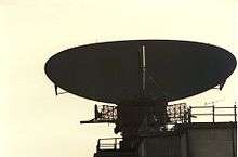
The Marconi AMES Type 84 was a primary "L" band radar. The main transmitting equipment was contained in a building over which the aerial was mounted; this building was given the type designation "R17". The transmitter was a magnetron in the single storey building, the signal passing through a rotating joint in the rotating cabin before being fed to the hornstacks on the aerial. The aerial was designed as two 60 foot by 21 foot elliptical parabolic antennas placed back-to-back, one acting as the radar, and the other as an IFF/secondary radar system. In practice the original IFF system was never installed, and instead more modern systems with much smaller antennas were installed on the "front" dish, either below the feed horn, or on top of the main antenna.
The received signals from both the primary and secondary radars were processed at the main technical building for the Linesman site, the R12 building.
Primary radar T85
The AEI (later Marconi) AMES Type 85 "Blue Yeoman" radar operated in the "S" band part of the spectrum. By comparison with the Type 84 it was massive, a MOPA system with 12 klystron transmitters and 60 receivers. The equipment was housed in the main technical block for the Radar site, the R12 building, the aerial being mounted on top of the building. The Type 85 ended up using the same design of antenna, although only "one side" of it, the aerial for the associated secondary radar being mounted underneath, rather than above.
The Type 85, however, offered an extremely advanced ECCM system enabling the shifting frequencies on the fly, or as it is now known frequency agility. The radar had 12 transmitters which were grouped in four bands, A, B, D & E. Each transmitter had a peak power output of 5 MW, giving 60 MW total power output, this massive power was routed through waveguide switches that enabled the aerial to produce a standard "cosec squared" beam or, in conditions of intense ECM the power concentrated into a beam 6 degrees high aimed at the target.
As well as the frequency agility and sheer power the Type 85 had multiple receivers enabling the return signals to be detected through the heaviest jamming, this included "dicky fix" receivers to combat carcinotron jamming. Post reception processing, including double integration loops enabling the comparison and discarding of spurious returns enhanced the ECCM capability still further. Whilst not having the Moving Target Indicator (MTI) facility the Type 84 had, the frequency band and processing ensured the Type 85 produced a clear picture even under the most arduous conditions.
As the transmission and reception of the Type 85 was based on 12 beams it was also a 3D radar. Data from the radar was passed to the Automatic Height Finder which compared comparative strength of returns from a target between beams. Given the range and known angle it is a simple process to calculate height. However this was being done hundreds of times a second on multiple targets, in the late 1960s and early 1970s it was a considerable feat.
Secondary radar
The secondary radar used in the system was the Cossor SSR750. Each primary radar had an associated secondary radar, at RAF Staxton Wold and RAF Neatishead there was an additional "freestanding" SSR. Secondary Radar information was associated with the primary (search) radar and presented on the same display. This gave operators a range of information that far exceeded the traditional, 'range and direction". The secondary radar was a dual military and civil system that worked by interrogating a transponder on board the aircraft, receiving and translating a coded reply.
Decoding SSR signals was carried out at L1 with the decoders supplied by Elliott Automation.
Height finding
There were three height finding facilities within the Linesman system. One was built into the Type 85 radar, the second was a stand-alone system using the HF200 radar and the third was based on the SSR interrogating the aircraft's systems.
The Type 85 working with the Auto Height Computer Type 12493 enabled an operator to select a target and, by triangulation in the radar's 12 beams, obtain a height.
The HF200 provided another means of finding the height of a target. This radar, rather than continuously rotating, nodded on a bearing selected by the operator. The bearing derived from the main primary radar would enable a reading of the height to be sent back to the operator.
The secondary radar system SSR750 as part of the joint military civil functionality could interrogate a transponder on board as aircraft for the height. This height, automatically derived from the onboard altimeter, was in the late 1960s and early 1970s shown to the operator on a box mounted above his screen. Later, with the advent of plot extraction it could be displayed alongside the aircraft on the traditional Plan position indicator (PPI) display.
Passive detection
A third system was later added to the network, the RX12874 "Winkle" passive jamming-detection system or PD system. PD consisted of a series of high-speed rotating antennas mounted on R15 buildings separated by many miles, combined with similar signals captured from a Type 85 radar.
The three Type 85 radars located at Neatishead, Staxton Wold, and Boulmer used the associated high speed PD aerials to make a PD baseline. For this the two aerials (T85 and PD) 100 miles apart had to be in sync to ensure they swept the same area of sky at the same time, sync and turning information was sent over microwave link. For example, the Type 85 at Neatishead used the signals captured from the high speed aerial at Staxton Wold to detect jamming aircraft. Each Type 85 with its associated high speed aerial was able to provide a PD baseline of several hundred miles to the north and south. There was a high speed aerial situated at Dundonald Hill in Ayrshire, Scotland which provided a baseline to the north of RAF Boulmer, but there was no similar extension to the south of RAF Neatishead.
The signals were combined at one of the radar stations (at the location of the Type 85 forming one end of the baseline) in a phase correlator that produced a series of possible locations and plotted them as a series of blips on a unique "theta-phi" display. The operators manually adjusted gains in order to reduce the number of blips, and then sent that information to a remote display where it could be combined with normal data from the Type 85. The idea was to locate any specialty-equipped jammer aircraft within a larger attack, allowing them to be prioritized for attack, thereby lowering the ECM load on other radars.
Operational training
Such a complex system required that Operators be fully trained. To this end L1 had a large, digital radar simulator that was capable of generating all the radar inputs of the live system. It was ordered from Elliott Automation following the successful development of the world's first digital radar simulator by that company. Based on the Elliot 502 computer it could simulate 6 radar heads with jamming and noise while displaying over 200 aircraft.
Operation
Linesman and L1 as originally conceived never became operational. It went operational in the early 1970s but only in producing and disseminating the overall Recognised Air Picture, the General Situation Display and the Higher Formation display until 1984. The interception side was only ever used in the training role of the School of Fighter Control. The L1 also got 3 more computers (Elliott Argus 500s) as the Recognised Air Picture Dissemination System (RAPiDS) and these disseminated the RAP out from the L1 in a more advanced format. Though the concepts remained very valid, the technology used to route the radar signals was out of date long before the system was completed. Having the control of aircraft centralised in one place also put it at high risk. A change of plan moved the interception roles out to two of the main radar stations where the RAP from the L1 was used to monitor the airspace while the Fighter Controllers then used the Standby Local Early Warning and Control Systems (SLEWC based on Elliott 920C computers) to control Interceptions.
In the original design processed radar signals were returned from the radar station to L1 and LATCC via microwave links. In the 1960s and 1970s this consisted of processed, but by today's standard raw, video and turning information (i.e. the angle of azimuth of the radar aerial). Received signals from the PD equipment and aerial turning synchronisation information were transmitted over the same links.
In the late 1970s plot extraction equipment was introduced, this took the primary and associated secondary radar outputs, combined and processed them before sending them over telephone lines to the L1. The RPEARDS (Radar Plot Extraction And Remote Display Equipment) was a hard-wired computer that processed, combined and transmitted the signals. The memory was magnetic core store that had the capacity of some 1000 words, each of over 60 bits in length, transmission over the telephone line was at 2400 baud using GMSK. At the time it was leading edge technology.
Legacy
Linesman built on Rotor which had built on Chain Home and the lessons of the Second World War. During the dangerous and tense period that was the Cold War, where the detection and interception of Russian bombers was a weekly, if not daily, event, Linesman enabled the protection and policing of UK air space. IUKADGES and subsequent developments have all built on the legacy of these systems, systems which stem from the Dowding System. An air defence system that enables the quick and accurate deployment of assets to intercept a threat conserves resources and targets them to where they are of the most use.
Conceived, proven and tested in the heat of the Battle of Britain the system is still sound even if the technology has improved many times and the threat since 9/11 has been significantly altered.
Whilst a lot of the evidence of Linesman systems and their associated above ground installations has gone, it is still possible to get a feeling for what operating and working at the height of the Cold War was like at the RAF Air Defence Radar Museum at RAF Neatishead.
See also
External links
- Radar Type 85 at radarpages.co.uk
- "Air traffic control in the seventies" – a 1970 Flight article on the Linesman/Mediator system