LNG carrier
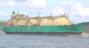
An LNG carrier is a tank ship designed for transporting liquefied natural gas (LNG). As the LNG market grows rapidly,[1] the fleet of LNG carriers continues to experience tremendous growth.
History
The first LNG carrier Methane Pioneer (5,034 DWT) left the Calcasieu River on the Louisiana Gulf coast on 25 January 1959. Carrying the world's first ocean cargo of LNG, it sailed to the UK where the cargo was delivered. Subsequent expansion of that trade has brought on a large expansion of the fleet to today where giant LNG ships carrying up to 266,000 m3 (9,400,000 cu ft) are sailing worldwide.
The success of the specially modified C1-M-AV1-type standard ship Normarti, renamed Methane Pioneer, caused the Gas Council and Conch International Methane Ltd. to order two purpose built LNG carriers to be constructed: Methane Princess and Methane Progress. The ships were fitted with Conch independent aluminum cargo tanks and entered the Algerian LNG trade in 1964. These ships had a capacity of 27,000 cubic metres (950,000 cu ft).
In the late 1960s, opportunity arose to export LNG from Alaska to Japan, and in 1969 that trade with TEPCO and Tokyo Gas was initiated. Two ships, Polar Alaska and Arctic Tokyo, each with a capacity of 71,500 cubic metres (2,520,000 cu ft), were built in Sweden. In the early 1970s, the US government encouraged US shipyards to build LNG carriers, and a total of 16 LNG ships were built. The late 1970s and early 1980s brought the prospect of Arctic LNG ships with a number of projects being studied.
With the increase in cargo capacity to approximately 143,000 cubic metres (5,000,000 cu ft), new tank designs were developed, from Moss Rosenberg to Technigaz Mark III and Gaztransport No.96.
In recent years, the size and capacity of LNG carriers has increased greatly.[2] Since 2005, Qatargas has pioneered the development of two new classes of LNG carriers, referred to as Q-Flex and Q-Max. Each ship has a cargo capacity of between 210,000 and 266,000 cubic metres (7,400,000 and 9,400,000 cu ft) and is equipped with a re-liquefaction plant.
Today we see interest for small scale LNG bunker carriers. Some need to stay below the life rafts of Cruise ships and Ropax vessels. Examples are the Damen LGC 3000 (http://products.damen.com/en/ranges/liquefied-gas-carrier) and the Seagas.
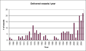
As of 2005, a total of 203 vessels had been built, of which 193 were still in service. At the end of 2016, the global LNG shipping fleet consisted of 439 vessels.[3] In 2017, an estimated 170 vessels are in use at any one time.[4]
New building
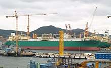
According to Tradewinds data, in January 2017 there were 122 new builds on order. The majority of new ships under construction are in the size of 120,000–140,000 m3 (4,200,000–4,900,000 cu ft), but there are orders for ships with capacity up to 260,000 m3 (9,200,000 cu ft). As of 2016, there were 451 LNG ships engaged in the deepsea movement of LNG.[5]
In 2017, Daewoo Shipbuilding & Marine Engineering delivered the Christophe de Margerie, an icebreaking LNG tanker of 80,200 deadweight tons. Her capacity of 172,600 m3 (6,100,000 cu ft) is the consumption of Sweden for a month.[6] She completed her first revenue voyage from Norway via the Northern Sea Route in the Arctic Ocean to South Korea.[7] The shipyard has fourteen more on order.[8]
In the case of small scale LNG carriers (LNG carriers below 40,000 m3 (1,400,000 cu ft)), the optimal size of a ship is determined by the project for which it is built, taking into consideration volume, destination and vessel characteristics.[9]
In 2018 South Koreas first LNG powered bulk carrier (Green Iris) will begin construction. It will have at time of writing the worlds largest capacity (50'000 tons).[10]
List of small scale LNG carrier builders:
Cargo handling
A typical LNG carrier has four to six tanks located along the center-line of the vessel. Surrounding the tanks is a combination of ballast tanks, cofferdams and voids; in effect, this gives the vessel a double-hull type design.
Inside each tank there are typically three submerged pumps. There are two main cargo pumps which are used in cargo discharge operations and a much smaller pump which is referred to as the spray pump. The spray pump is used for either pumping out liquid LNG to be used as fuel (via a vaporizer), or for cooling down cargo tanks. It can also be used for "stripping" out the last of the cargo in discharge operations. All of these pumps are contained within what is known as the pump tower which hangs from the top of the tank and runs the entire depth of the tank. The pump tower also contains the tank gauging system and the tank filling line, all of which are located near the bottom of the tank.
In membrane-type vessels there is also an empty pipe with a spring-loaded foot valve that can be opened by weight or pressure. This is the emergency pump tower. In the event both main cargo pumps fail the top can be removed from this pipe and an emergency cargo pump lowered down to the bottom of the pipe. The top is replaced on the column and then the pump is allowed to push down on the foot valve and open it. The cargo can then be pumped out.
All cargo pumps discharge into a common pipe which runs along the deck of the vessel; it branches off to either side of the vessel to the cargo manifolds, which are used for loading or discharging.
All cargo tank vapour spaces are linked via a vapour header which runs parallel to the cargo header. This also has connections to the sides of the ship next to the loading and discharging manifolds.
Typical cargo cycle
A typical cargo cycle starts with the tanks in a "gas free" condition, meaning the tanks are full of air, which allows maintenance on the tank and pumps. Cargo cannot be loaded directly into the tank, as the presence of oxygen would create an explosive atmospheric condition within the tank, and the rapid temperature change caused by loading LNG at −162 °C (−260 °F) could damage the tanks.
First, the tank must be 'inerted' to eliminate the risk of explosion. An inert gas plant burns diesel in air to produce a mixture of gases (typically less than 5% O2 and about 13% CO2 plus N2). This is blown into the tanks until the oxygen level is below 4%.
Next, the vessel goes into port to "gas-up" and "cool-down", as one still cannot load directly into the tank: The CO2 will freeze and damage the pumps and the cold shock could damage the tank's pump column.
LNG is brought onto the vessel and taken along the spray line to the main vaporiser, which boils off the liquid into gas. This is then warmed up to roughly 20 °C (68 °F) in the gas heaters and then blown into the tanks to displace the "inert gas". This continues until all the CO2 is removed from the tanks. Initially, the IG (inert gas) is vented to atmosphere. Once the hydrocarbon content reaches 5% (lower flammability range of methane) the inert gas is redirected to shore via a pipeline and manifold connection by the HD (high duty) compressors. The shore terminal then burns this vapour to avoid the dangers of having large amounts of hydrocarbons present which may explode.
Now the vessel is gassed up and warm. The tanks are still at ambient temperature and are full of methane.
The next stage is cool-down. LNG is sprayed into the tanks via spray heads, which vaporises and starts to cool the tank. The excess gas is again blown ashore to be re-liquified or burned at a flare stack. Once the tanks reach about −140 °C (−220 °F) the tanks are ready to load bulk.
Bulk loading starts and liquid LNG is pumped from the storage tanks ashore into the vessel tanks. Displaced gas is blown ashore by the HD compressors. Loading continues until typically 98.5% full is reached (to allow for thermal expansion/contraction of cargo).
The vessel can now proceed to the discharge port. During passage various boil-off management strategies can be used. Boil-off gas can be burned in boilers to provide steam for propulsion, or it can be re-liquefied and returned to the cargo tanks, depending on the design of the vessel.
Once in the discharge port, the cargo is pumped ashore using the cargo pumps. As the tank empties, the vapour space is filled by either gas from ashore or by vaporising some cargo in the cargo vaporiser. Either the vessel can be pumped out as far as possible, with the last being pumped out with spray pumps, or some cargo can be retained on board as a "heel".
It is normal practice to keep onboard 5% to 10% of the cargo after discharge in one tank. This is referred to as the heel and this is used to cool down the remaining tanks that have no heel before loading. This must be done gradually otherwise the tanks will be cold shocked if loaded directly into warm tanks. Cool-down can take roughly 20[11] hours on a Moss vessel (and 10–12 hours on a membrane type vessel), so carrying a heel allows cool-down to be done before the vessel reaches port giving a significant time saving.
If all the cargo is pumped ashore, then on the ballast passage the tanks will warm up to ambient temperature, returning the vessel to a gassed up and warm state. The vessel can then be cooled again for loading.
If the vessel is to return to a gas free state, the tanks must be warmed up by using the gas heaters to circulate warm gas. Once the tanks are warmed up, the inert gas plant is used to remove the methane from the tanks. Once the tanks are methane free, the inert gas plant is switched to dry air production, which is used to remove all the inert gas from the tanks until they have a safe working atmosphere.
Transportation of natural gas both in the form of LNG and by pipeline causes greenhouse gas emissions, but in different ways. With pipelines, most of the emissions stem from the production of steel pipe; with LNG most of the emissions stem from liquefaction. For both pipelines and LNG, propulsion causes additional emissions (pressurization of the pipeline, propulsion of the LNG tanker).[12]
Containment systems
Today there are four containment systems in use for new build vessels. Two of the designs are of the self-supporting type, while the other two are of the membrane type and today the patents are owned by Gaz Transport & Technigaz (GTT).
There is a trend towards the use of the two different membrane types instead of the self-supporting storage systems. This is most likely because prismatic membrane tanks utilize the hull shape more efficiently and thus have less void space between the cargo-tanks and ballast tanks. As a result of this, Moss-type design compared to a membrane design of equal capacity will be far more expensive to transit the Suez Canal. However, self-supporting tanks are more robust and have greater resistance to sloshing forces, and will possibly be considered in the future for offshore storage where bad weather will be a significant factor.
Moss tanks (Spherical IMO type B LNG tanks)
.PNG)
Named after the company that designed them, the Norwegian company Moss Maritime, the Spherical IMO type B LNG tanks are spherical in shape. Most Moss type vessels have 4 or 5 tanks.
The outside of the tank has a thick layer of foam insulation that is either fitted in panels or in more modern designs wound round the tank. Over this insulation is a thin layer of "tinfoil" which allows the insulation to be kept dry with a nitrogen atmosphere. This atmosphere is constantly checked for any methane that would indicate a leak of the tank. Also the outside of the tank is checked at 3 month intervals for any cold spots that would indicate breakdown in the insulation.
The tank is supported around its circumference by the equatorial ring, which is supported by a large circular skirt, known as a data-couple that is a unique combination of aluminum and steel, which takes the weight of the tank down to the ships structure. This skirt allows the tank to expand and contract during cool-down and warm-up operations. During cool-down or warm-up the tank can expand or contract about 60 cm (24 in). Because of this expansion and contraction all piping into the tank comes in the top and is connected to the ships lines via flexible bellows.
Inside each tank there is a set of spray heads. These heads are mounted around the equatorial ring and are used to spray Liquid LNG onto the tank walls to reduce the temperature.
Tanks normally have a working pressure of up to 22 kPa (3.2 psi), but this can be raised for an emergency discharge. If both main pumps fail then to remove the cargo, the tank's safety valves are adjusted to lift at 100 kPa. Then the filling line which goes to the bottom of the tank is opened along with the filling lines of the other tanks on board. The pressure is then raised in the tank with the defective pumps which pushes the cargo into the other tanks where it can be pumped out.
IHI (Prismatic IMO type B LNG tanks)
Designed by Ishikawajima-Harima Heavy Industries, the self-supporting prismatic type B (SPB) tank is currently employed in only two vessels. Type B tanks limit sloshing problems, an improvement over Membrane LNG carrier tanks which may break due to sloshing impact, therefore destroying the ship's hull. This is also of prime relevance for FPSO LNG (or FLNG).
In addition, IMO type B LNG tanks can sustain internal accidental damage due for example to internal equipment releases. This was incorporated into the design following several incidents that occurred inside membrane LNG tanks.
TGZ Mark III
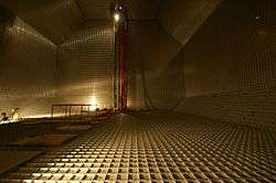
Designed by Technigaz, these tanks are of the membrane type. The membrane consists of stainless steel with 'waffles' to absorb the thermal contraction when the tank is cooled down. The primary barrier, made of corrugated stainless steel of about 1.2 mm (0.047 in) thickness is the one in direct contact with the cargo liquid (or vapour in empty tank condition). This is followed by a primary insulation which in turn is covered by a secondary barrier made of a material called "triplex" which is basically a metal foil sandwiched between glasswool sheets and compressed together. This is again covered by a secondary insulation which in turn is supported by the ship's hull structure from the outside.[13][14]
From the inside of the tank outwards, the layers are:
- LNG
- Primary barrier of 1.2 mm thick corrugated/waffled 304L stainless steel
- Primary insulation (also called the interbarrier space)
- Secondary barrier within triplex membrane
- Secondary insulation (also called the insulation space)
- Ship's hull structure.
GT96
Designed by Gaz Transport, the tanks consists of a primary and secondary thin membrane made of the material Invar which has almost no thermal contraction. The insulation is made out of plywood boxes filled with perlite and continuously flushed with nitrogen gas. The integrity of both membranes is permanently monitored by detection of hydrocarbon in the nitrogen. An evolution is proposed by NG2, with the replacement of nitrogen by argon as the flushed inert and insulation gas. Argon has a better insulation power than nitrogen, which could save 10% of boil-off gas.[14][15]
CS1
CS1 stands for Combined System Number One. It was designed by the now merged Technigaz and GazTransport companies and consists of the best components of both MkIII and No96 systems. The primary barrier is made of invar 0.7 mm (0.028 in), and secondary from Triplex. The primary and secondary insulation consists of polyurethane foam panels.
Three vessels with CS1 technology have been built by one shipyard, but established shipyards have decided to maintain production of the MKIII and NO96.
Reliquefaction and boil-off
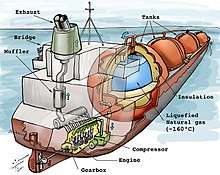
In order to facilitate transport, natural gas is cooled down to approximately −163 °C (−261 °F) at atmospheric pressure, at which point the gas condenses to a liquid. The tanks on board an LNG carrier effectively function as giant thermoses to keep the liquid gas cold during storage. No insulation is perfect, however, and so the liquid is constantly boiling during the voyage.
According to WGI, on a typical voyage an estimated 0.1–0.25% of the cargo converts to gas each day, depending on the efficiency of the insulation and the roughness of the voyage.[16] In a typical 20-day voyage, anywhere from 2–6% of the total volume of LNG originally loaded may be lost.[16]
Normally an LNG tanker is powered by steam turbines with boilers. These boilers are dual fuel and can run on either methane or oil or a combination of both.
The gas produced in boil off is traditionally diverted to the boilers and used as a fuel for the vessel. Before this gas is used in the boilers, it must be warmed up to roughly 20 °C by using the gas heaters. The gas is either fed into the boiler by tank pressure or it is increased in pressure by the LD compressors.
What fuel the vessel runs on is dependent on many factors which include the length of the voyage, desire to carry a heel for cooldown, price of oil versus price of LNG.
There are three basic modes available:
Minimum boil-off/maximum oil:- In this mode tank pressures are kept high to reduce boil off to a minimum and the majority of energy comes from the fuel oil. This maximises the amount of LNG delivered but does allow tank temps to rise due to lack of evaporation. The high cargo temps can cause storage problems and offloading problems.
Maximum boil-off/minimum oil:- In this mode the tank pressures are kept low and you have a greater boil-off but still there is a large amount of fuel oil used. This decreases the amount of LNG delivered but the cargo will be delivered cold which many ports prefer.
100% gas:- Tank pressures are kept at a similar level to max boil off but this is not enough to supply all the boilers needs so you must start to "force". A small pump is started in one tank to supply LNG to the forcing vaporiser, where the LNG is warmed and vaporized back into a gas that is usable in the boilers. In this mode no fuel oil is used.
Recent advances in technology reliquefication plants to be fitted to vessels, allowing the boil off to be reliquefied and returned to the tanks. Because of this, the vessels' operators and builders have been able to contemplate the use of more efficient slow-speed Diesel engines (previously most LNG carriers have been steam turbine-powered). Exceptions are the LNG carrier Havfru (built as Venator in 1973), which originally had dual fuel diesel engines, and its sister-ship Century (built as Lucian in 1974), also built with dual fuel gas turbines before being converted to a diesel engine system in 1982.
Vessels using Dual or Tri-Fuel Diesel Electric, respectively DFDE e TFDE, propulsion systems are now in service.
Consequences of spillage
While no measures exist to prevent all accidents, several past major petrochemical spills, such as the Exxon Valdez or the Deepwater Horizon oil drilling rig spills, have caused a sense of rising concern within the industry.
Compared to oil, there is less public concern over spillage of Liquid Natural Gas (LNG) carrying vessels . The LNG sector is known to have a good safety record regarding cargo loss. There have been close to 80,000 loaded port transits of LNG carriers with no loss of containment failure.[17](Pitblado, 2004)
An analysis of several spherical carriers showed that the vessels can withstand a 90 degree side-on collision with another similar LNG carrier at 6.6kts (50% of normal port speed) with no loss of LNG cargo integrity.[18] This drops to 1.7kts for a fully loaded 300,000 dwt oil tanker collision into an LNG carrier. The report also notes that such collisions are rare, though are possible.[17] (Pitblado, 2004)
HAZID performed a risk assessment of an LNG spill. Taking into account precautions, training, regulations and technology changes over time HAZID calculates that the likelihood of an LNG spill as approximately 1 in 100,000 trips.[17] (Pitblado, 2004)
In the event that the tank integrity of a LNG transport is compromised, there is a risk that the natural gas contained within could ignite, causing either an explosion or fire.[19]
See also
| Wikimedia Commons has media related to LNG carriers. |
References
- ↑ The Global Liquefied Natural Gas Market: Status and Outlook
- ↑ Ulvestad, Marte; Overland, Indra (2012). "Natural gas and CO2 price variation: Impact on the relative cost-efficiency of LNG and pipelines". "International Journal of Environmental Studies". 69 (3): 407–426.
- ↑ "2017 World LNG Report" (PDF). IGU(International Gas Union).
- ↑ Gold, Russell (7 June 2017). "Global market for natural gas has finally arrived". The Australian. Retrieved 7 June 2017.
- ↑ "Archived copy". Archived from the original on 6 August 2010. Retrieved 29 July 2010.
- ↑ "Unique ice-breaking LNG carrier Christophe de Margerie ready to serve Yamal LNG project". Hellenic Shipping News. March 31, 2017. Retrieved 24 August 2017.
- ↑ McGrath, Matt (24 August 2017). "First tanker crosses northern sea route without ice breaker". BBC. Retrieved 24 August 2017.
- ↑ "Christophe de Margerie Class Icebreaking LNG Carriers, Russia". Ship Technology. Retrieved 24 August 2017.
- ↑ Small Scale Carrier Optimal Vessel Size Calculator
- ↑ "Korea's first LNG-fueled bulk carrier goes in service next year | Hellenic Shipping News Worldwide". www.hellenicshippingnews.com. Retrieved 2018-01-07.
- ↑ GIIGNL Fourth Edition 2.6.2
- ↑ Ulvestad, Marte; Overland, Indra (2012). "Natural Gas and CO2 price variation: Impact on the relative cost-efficiency of LNG and pipelines". International Journal of Environmental Studies. 69: 407–426 – via https://www.researchgate.net/publication/261221877.
- ↑ "GTT Mark III Technology". Gaztransport & Technigaz (GTT) via YouTube. Nov 7, 2013.
- 1 2 "Membrane Containment System". North West Shelf Shipping Services Company (NWSSSC) Pty. Limited. 2014.
- ↑ "GTT NO 96 Technology". Gaztransport & Technigaz (GTT) via YouTube. Nov 7, 2013.
- 1 2 World Gas Intelligence, 30 July 2008
- 1 2 3 Pitblado. "Consequences of LNG marine incidents" (PDF). www.energy.ca.gov.
- ↑ Mokhatab, Saeid; Mak, John Y.; Valappil, Jaleel V.; Wood, David A. (2013-10-15). Handbook of Liquefied Natural Gas. Gulf Professional Publishing. ISBN 9780124046450.
- ↑ "Methane: The other important greenhouse gas". Environmental Defense Fund. Retrieved 15 November 2017.
Modern merchant ships | ||
|---|---|---|
| Dry cargo | ||
| Tankers | ||
| Passenger | ||
| Support | ||
| Other | ||