IBM 3270
The IBM 3270 is a class of block oriented computer terminals (sometimes called display devices) introduced by IBM in 1971[1] normally used to communicate with IBM mainframes. The 3270 was the successor to the IBM 2260 display terminal. Due to the text colour on the original models, these terminals are informally known as green screen terminals. Unlike a character-oriented terminal, the 3270 minimizes the number of I/O interrupts required by transferring large blocks of data known as data streams, and uses a high speed proprietary communications interface, using coaxial cable.
Although IBM no longer manufactures 3270 terminals, the IBM 3270 protocol is still commonly used via terminal emulation to access mainframe-based applications. Accordingly, such applications are sometimes referred to as green screen applications. The use of 3270 is slowly diminishing as more and more mainframe applications acquire Web interfaces, although some Web applications merely use the technique of "screen scraping" to capture old screens and transfer the data to modern front-ends.
Principles
The 3270 series was designed to connect with mainframe computers, often at a remote location, using the technology then available in the early 1970s. The main goal of the system was to maximize the number of terminals that could be used on a single mainframe. To do this, the 3270 was designed to minimize the amount of data transmitted, and minimize the frequency of interrupts to the mainframe. By ensuring the CPU is not interrupted at every keystroke, a 1970s-era IBM 3033 mainframe with only 16 MB was able to support up to 17,500 3270 terminals under CICS.

3270 devices are clustered, with one or more displays or printers connected to a control unit (the 3275 and 3276 included an integrated control unit). Originally devices were connected to the control unit over coaxial cable; later token ring, twisted pair, or Ethernet connections were available. A local control unit attaches directly to the channel of a nearby mainframe. A remote control unit is connected to a communications line by a modem. Remote 3270 controllers are frequently multi-dropped, with multiple control units on a line.
In a data stream, both text and control (or formatting functions) are interspersed allowing an entire screen to be "painted" as a single output operation. The concept of formatting in these devices allows the screen to be divided into fields (clusters of contiguous character cells) for which numerous field attributes (colour, highlighting, character set, protection from modification) can be set. A field attribute occupies a physical location on the screen that also determines the beginning and end of a field.
Using a technique known as "read modified", a single transmission back to the mainframe can contain the changes from any number of formatted fields that have been modified, but without sending any unmodified fields or static data. This technique enhances the terminal throughput of the CPU, and minimizes the data transmitted. Some users familiar with character interrupt-driven terminal interfaces find this technique unusual. There is also a "read buffer" capability that transfers the entire content of the 3270-screen buffer including field attributes. This is mainly used for debugging purposes to preserve the application program screen contents while replacing it, temporarily, with debugging information.
Early 3270s offered three types of keyboards. The typewriter keyboard came in both a 66 key version, with no programmed function (PF) keys, and a 78 key version with twelve. Both versions had two program attention (PA) keys. The data entry keyboard had five PF keys and two PA keys. The operator console keyboard had twelve PF keys and two PA keys.[2]:p.19 Later 3270s had twenty-four PF keys and three PA keys. When one of these keys is pressed, it will cause its control unit to generate an I/O interrupt to the host computer and present a special code identifying which key was pressed. Application program functions such as termination, page-up, page-down, or help can be invoked by a single key press, thereby reducing the load on very busy processors.
A downside to this approach was that vi-like behaviour, responding to individual keystrokes, was not possible. For the same reason, a porting of Lotus 1-2-3 to mainframes with 3279 screens did not meet with success because its programmers were not able to properly adapt the spreadsheet's user interface to a "screen at a time" rather than "character at a time" device. But end-user responsiveness was arguably more predictable with 3270, something users appreciated.
Applications
Following its introduction the 3270 and compatibles were by far the most commonly used terminals on IBM System/370 and successor systems.[3] IBM and third-party software that included an interactive component took for granted the presence of 3270 terminals and provided a set of ISPF panels and supporting programs.
Conversational Monitor System (CMS) in VM/SP has support for the 3270.
Time Sharing Option (TSO) in OS/360 and successors has line mode command line support and also has facilities for full screen applications, e.g., ISPF.
Device independent Display Operator Console Support (DIDOCS) in Multiple Console Support (MCS) for OS/360 and successors.
The SPF and Program Development Facility (ISPF/PDF) editors for MVS and VM/SP (ISPF/PDF was available for VM, but little used) and XEDIT editors for VM/SP respectively make extensive use of 3270 features.
Customer Information Control System (CICS) has support for 3270 panels.
Various versions of Wylbur have support for 3270, including support for full-screen applications.
The modified data tag is well suited to converting formatted, structured punched card input onto the 3270 display device. With the appropriate programming, any batch program that uses formatted, structured card input can be layered onto a 3270 terminal.
IBM's OfficeVision office productivity software enjoyed great success with 3270 interaction because of its design understanding. And for many years the PROFS calendar was the most commonly displayed screen on office terminals around the world.
A version of the WordPerfect word processor ported to System/370 was designed for the 3270 architecture.
3270 and The Web (and HTTP) are similar in that both follow a thin client client-server architecture whereby they, the clients, are given primary responsibility for managing presentation and user input. This minimizes host interactions while still facilitating server-based information retrieval and processing.
With the arrival of the web, application development has in many ways returned to the 3270 approach. In the 3270 era, all application functionality was provided centrally. With the advent of the PC, the idea was to invoke central systems only when absolutely unavoidable, and to do all application processing with local software on the personal computer. Now in the web era (and with wikis in particular), the application again is strongly centrally controlled, with only technical functionality distributed to the PC.
In the early 1990s a popular solution to link PCs with the mainframes was the Irma board, an expansion card that plugged into a PC and connected to the controller through a coaxial cable. IRMA also allows file transfers between the PC and the mainframe.
Third parties
One of the first groups to write and provide operating system support for the 3270 and its early predecessors was the University of Michigan, who created the Michigan Terminal System in order for the hardware to be useful outside of the manufacturer. MTS was the default OS at Michigan for many years, and was still used at Michigan well into the 1990s. Many manufacturers, such as GTE, Hewlett Packard, Honeywell/Incoterm Div, Memorex, ITT Courier and Teletype/AT&T created 3270 compatible[4] terminals, or adapted ASCII terminals such as the HP 2640 series to have a similar block-mode capability that would transmit a screen at a time, with some form validation capability. Modern applications are sometimes built upon legacy 3270 applications, using software utilities to capture (screen scraping) screens and transfer the data to web pages or GUI interfaces.
Models
The IBM 3270 display terminal subsystem consists of displays, printers and controllers. Optional features for the 3275 and 3277 are the selector-pen or light pen, ASCII rather than EBCDIC character set, an audible alarm, and a keylock for the keyboard. A keyboard numeric lock was available and will lock the keyboard if the operator attempts to enter non-numeric data into a field defined as numeric.[2] Later an Operator Identification Card Reader was added which could read information encoded on a magnetic stripe card.
Displays
- 3277 model 1: 40×12 terminal
- 3277 model 2: 80×24 terminal, the biggest success of all
- 3277 GA: a 3277 with an RS232C I/O, often used to drive a Tektronix 4013 or 4015 graphic screen (monochrome)
- 3278 models 1–5: next-generation, with accented characters and dead keys in countries that needed them
- model 1: 80x12
- model 2: 80×24
- model 3: 80×32 or 80x24 (switchable)
- model 4: 80×43 or 80x24 (switchable)
- model 5: 132×27 or 80×24 (switchable)
- 3278 PS: programmable characters; able to display monochrome graphics
- 3279: colour terminal, 4-colour (text) or 7-colour (graphics) version
- 3290: a large, amber monochrome plasma display unit, capable of displaying in various modes, including four independent 3278 model 2 terminals, or a single 160×62 terminal; it also supported partitioning.[5]
- 3178: lower cost terminal (1983)
- 3179: low cost colour terminal (1984)
- 3104: low-cost R-loop connected terminal for the IBM 8100 system
- 3472 Infowindow
(Generally, 3277 models allow only upper-case input, except for the mixed EBCDIC/APL or text keyboards, which have lower case. Lower-case capability and possibility of dead keys, at first a simple RPQ (Request Price Quotation, tailored on request at extra cost) were only added in 3278 & 3279 models.)
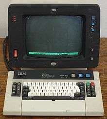
A version of the IBM PC called the 3270 PC, released in October 1983, includes 3270 terminal emulation. Later, the 3270 PC/G (graphics) and 3270 PC/GX (extended graphics) followed.
Display-Controller
- 3275 remote display with controller function (no additional displays up to one printer)
- 3276 remote display with controller function (up to a limited number of displays or printers)
Printers
- 3284 matrix printer
- 3286 matrix printer
- 3287 printer, including a colour model
- 3288 line printer
- 3268-1 : R-loop connected stand-alone printer for the IBM 8100 system
Controllers
- 3271 remote controller
- 3272 local controller
- 3274 cluster controller (different models could be channel-attached or remote via BSC or SDLC communication lines, and had between eight and 32 co-ax ports)
- 3174 cluster controller
By 1994 the "3174 Establishment Controller" supported features such as attachment to multiple hosts via token ring, Ethernet, or X.25 in addition to the standard channel attach or SDLC, and terminal attachment via twisted pair, token ring or Ethernet in addition to co-ax. They also support attachment of asynchronous ASCII terminals, printers, and plotters alongside 3270 devices.[6]
Manufacture
The IBM 3270 display terminal subsystem was designed and developed by IBM's Kingston, New York, laboratory (which later closed during IBM's difficult time in the mid-1990s). The printers were developed by the Endicott, New York, laboratory. As the subsystem expanded, the 3276 display-controller was developed by the Fujisawa, Japan, laboratory, and later the Yamato laboratory; and the 3279 colour display and 3287 colour printer by the Hursley, UK, laboratory. The subsystem products were manufactured in Kingston (displays and controllers), Endicott (printers), and Greenock, Scotland, UK, (most products) and shipped to users in U.S. and worldwide. 3278 terminals continued to be manufactured in Hortolândia, near Campinas, Brazil as far as late 1980s, having its internals redesigned by a local engineering team using modern CMOS technology, while retaining its external look and feel.
Telnet 3270
Telnet 3270, or tn3270 describes both the process of sending and receiving 3270 data streams using the Telnet protocol and the software that emulates a 3270 class terminal that communicates using that process. tn3270 allows a 3270 terminal emulator to communicate over a TCP/IP network instead of an SNA network. Telnet 3270 can be used for either terminal or print connections. Standard telnet clients cannot be used as a substitute for tn3270 clients, as they use fundamentally different techniques for exchanging data.
Technical Information
3270 character set
The following table shows the 3275/3277/3284/3286 character set for US English EBCDIC (optional characters were available for US ASCII, and UK, French, German, and Italian EBCDIC). The numbers are the equivalent Unicode code points.
On the 3275 and 3277 terminals without the a text feature, lower case characters display as uppercase. NL, EM, DUP, and FM control characters display and print as 5, 9, *, and ; characters, respectively, except by the printer when WCC or CCC bits 2 and 3 = '00'b, in which case NL and EM serve their control function and do not print.[2]:p.15
| _0 | _1 | _2 | _3 | _4 | _5 | _6 | _7 | _8 | _9 | _A | _B | _C | _D | _E | _F | |
|---|---|---|---|---|---|---|---|---|---|---|---|---|---|---|---|---|
| 0_ | NUL 0000 0 |
SOH 0001 1 |
STX 0002 2 |
ETX 0003 3 |
4 |
PT 5 |
6 |
7 |
8 |
9 |
10 |
11 |
FF 000C 12 |
13 |
14 |
15 |
| 1_ | DLE 0010 16 |
SBA 17 |
EUA 18 |
IC 19 |
20 |
NL 0085 21 |
22 |
23 |
24 |
EM 0019 25 |
26 |
27 |
DUP 28 |
SF 29 |
FM 30 |
ITB 31 |
| 2_ | 32 |
33 |
34 |
35 |
36 |
37 |
ETB 0017 38 |
ESC 001B 39 |
40 |
41 |
42 |
43 |
44 |
ENQ 0005 45 |
46 |
47 |
| 3_ | 48 |
49 |
SYN 0016 50 |
51 |
52 |
53 |
54 |
EOT 0004 55 |
56 |
57 |
58 |
59 |
RA 60 |
NAK 0015 61 |
62 |
SUB 001A 63 |
| 4_ | SP 0020 64 |
65 |
66 |
67 |
68 |
69 |
70 |
71 |
72 |
73 |
¢ 00A2 74 |
. 002E 75 |
< 003C 76 |
( 0028 77 |
+ 002B 78 |
| 007C 79 |
| 5_ | & 0026 80 |
81 |
82 |
83 |
84 |
85 |
86 |
87 |
88 |
89 |
! 0021 90 |
$ 0024 91 |
* 002A 92 |
) 0029 93 |
; 003B 94 |
¬ 00AC 95 |
| 6_ | - 002D 96 |
/ 002F 97 |
98 |
99 |
100 |
101 |
102 |
103 |
104 |
105 |
¦ 00A6 106 |
, 002C 107 |
% 0025 108 |
_ 005F 109 |
> 003E 110 |
? 003F 111 |
| 7_ | 112 |
113 |
114 |
115 |
116 |
117 |
118 |
119 |
120 |
121 |
: 003A 122 |
# 0023 123 |
@ 0040 124 |
' 0027 125 |
= 003D 126 |
" 0022 127 |
| 8_ | 128 |
a 0061 129 |
b 0062 130 |
c 0063 131 |
d 0064 132 |
e 0065 133 |
f 0066 134 |
g 0067 135 |
h 0068 136 |
i 0069 137 |
138 |
139 |
140 |
141 |
142 |
143 |
| 9_ | 144 |
j 006A 145 |
k 006B 146 |
l 006C 147 |
m 006D 148 |
n 006E 149 |
o 006F 150 |
p 0070 151 |
q 0071 152 |
r 0072 153 |
154 |
155 |
156 |
157 |
158 |
159 |
| A_ | 160 |
161 |
s 0073 162 |
t 0074 163 |
u 0075 164 |
v 0076 165 |
w 0077 166 |
x 0078 167 |
y 0079 168 |
z 007A 169 |
170 |
171 |
172 |
173 |
174 |
175 |
| B_ | 176 |
177 |
178 |
179 |
180 |
181 |
182 |
183 |
184 |
185 |
186 |
187 |
188 |
189 |
190 |
191 |
| C_ | 192 |
A 0041 193 |
B 0042 194 |
C 0043 195 |
D 0044 196 |
E 0045 197 |
F 0046 198 |
G 0047 199 |
H 0048 200 |
I 0049 201 |
202 |
203 |
204 |
205 |
206 |
207 |
| D_ | 208 |
J 004A 209 |
K 004B 210 |
L 004C 211 |
M 004D 212 |
N 004E 213 |
O 004F 214 |
P 0050 215 |
Q 0051 216 |
R 0052 217 |
218 |
219 |
220 |
221 |
222 |
223 |
| E_ | 224 |
225 |
S 0053 226 |
T 0054 227 |
U 0055 228 |
V 0056 229 |
W 0057 230 |
X 0058 231 |
Y 0059 232 |
Z 005A 233 |
234 |
235 |
236 |
237 |
238 |
239 |
| F_ | 0 0030 240 |
1 0031 241 |
2 0032 242 |
3 0033 243 |
4 0034 244 |
5 0035 245 |
6 0036 246 |
7 0037 247 |
8 0038 248 |
9 0039 249 |
250 |
251 |
252 |
253 |
254 |
255 |
| _0 | _1 | _2 | _3 | _4 | _5 | _6 | _7 | _8 | _9 | _A | _B | _C | _D | _E | _F |
Data stream
Data sent to the 3270 consists of commands and orders. Commands instruct the 3270 control unit to perform some action on a specified device, such a read or write. Orders are sent as part of the data stream to control the format of the device buffer.
The following description applies to the 3271, 3272, and 3275 control units. Later models of 3270 have additional capabilities.
Commands
| Command | hexadecimal Code (local) | Function[2] |
|---|---|---|
| Write | 01 | Writes data to the device |
| Erase/Write | 05 | Erases device buffer and writes data |
| Read Buffer | 02 | Reads entire device buffer, for example always 1920 bytes on a 3277-2 |
| Read Modified | 06 | Reads only modified data from device |
| Copy | N/A | (Remote only) Copies data from one device buffer to another, for example from a display to a printer attached to the same control unit |
| Select | 0B | Transfers data from device to control unit |
| Erase All Unprotected | 0F | Erases all unprotected data and resets modified data tags |
| No Operation | 03 | May be used to retrieve pending status |
| Sense | 04 | Retrieves error information after unit check |
| For remote 3270s non-significant bits are set so that the command forms a valid EBCDIC (or ASCII) character. |
Write control character
The data sent by Write or Erase/Write consists of the command code itself followed by a Write Control Character (WCC) optionally followed by a buffer containing orders or data (or both). The WCC controls the operation of the device. Bits may start printer operation and specify a print format. Other bit settings will sound the audible alarm if installed, unlock the keyboard to allow operator entry, or reset all the Modified Data Tags in the device buffer.
Orders
Orders consist of the order code byte followed by zero to three bytes of variable information.
| Order | Hexadecimal code (EBCDIC) | Description[2] | |||
|---|---|---|---|---|---|
| Byte 1 | Byte 2 | Byte 3 | Byte 4 | ||
| Start Field (SF) | 1D | Attribute character (see Attributes) | Indicates the start of a field at the current buffer position and provides its attribute | ||
| Set Buffer Address (SBA) | 11 | Address byte 1 | Address byte 2 | Specifies a buffer address to become the current buffer position (see Buffer addressing) | |
| Insert Cursor (IC) | 13 | Positions the cursor at the current buffer position | |||
| Program Tab (PT) | 05 | Advances the current buffer address to the first position of the next unprotected field | |||
| Repeat to Address (RA) | 3C | Address byte 1 | Address byte 2 | Character to repeat | Stores the character in byte 4 in all buffer locations starting at the current buffer position up to but not including the specified address and sets the current buffer position to the specified address |
| Erase Unprotected to Address (EUA) | 12 | Address byte 1 | Address byte 2 | Fills all unprotected fields with nulls starting at the current buffer position up to but not including the specified address | |
Attributes
The original 3277 and 3275 displays used an 8-bit field attribute byte of which five bits were used.[2]:p.18
- Bits 0 and 1 are set so that the attribute will always be a valid EBCDIC (or ASCII) character.
- Bit 2 is zero to indicate that the associated field is unprotected (operator could enter data) or one for protected.
- Bit 3 is zero to indicate that this field, if unprotected, could accept alphanumeric input. One indicates that only numeric input is accepted, and automatically shifts to numeric for some keyboards.
- Bit 4 and 5 operate in tandem:
- '00'B indicate that the field is displayed on the screen and is not selector-pen detectable.
- '01'B indicates that the field is displayable and selector-pen detectable.
- '10'B indicates that the field is intensified (bright), displayable, and selector-pen detectable.
- '11'B indicates that the field is non-display, non-printable, and not pen detectable. This last can be used in conjunction with the modified data tag to imbed static data on the screen that will be read each time data was read from the device.
- Bit 7 is the "Modified Data Tag", where '0' indicates that the associated field has not been modified by the operator and '1' indicates that it has been modified. As noted above, this bit can be set programmatically to cause the field to be treated as modified.
Later models include base colour support for four colours. "In base color mode, the protection and intensity bits are used in combination to select among four colors: normally white, red, blue, and green; the protection bits retain their protection functions as well as determining color."[7] Still later models used extended attributes to add support for seven colours, blinking, reverse video, underscoring, field outlining, field validation, and programmed symbols.[7] In addition, later models added character attributes, which could establish, e.g., color for individual characters without starting a new field or taking up a screen position.
Buffer addressing
3270 displays and printers have a buffer containing one byte for every screen position. For example, a 3277 model 2 featured a screen size of 24 rows of 80 columns for a buffer size of 1920 bytes. Bytes are addressed from zero to the screen size minus one, in this example 1919. "There is a fixed relationship between each ... buffer storage location and its position on the display screen."[2]:p.13 Most orders start operation at the "current" buffer address, and executing an order or writing data will update this address. The buffer address can be set directly using the Set Buffer Address (SBA) order, often followed by Start Field. For a device with a 1920 character display a twelve bit address is sufficient. Later 3270s with larger screen sizes use fourteen or sixteen bits.
Addresses are encoded in orders in two bytes. For twelve bit addresses the high order two bits of each byte are normally set to form valid EBCDIC (or ASCII) characters. For example, address 0 is coded as X'4040', or space-space, address 1919 is coded as X'5D7F', or ')"'.[2]:pp.75–90 Programmers hand coding panels usually keep the table of addresses from the 3270 Component Description or the 3270 Reference Card handy. For fourteen and sixteen bit address, the address uses contiguous bits in two bytes.
Example
The following data stream writes an attribute in row 24, column 1, writes the (protected) characters '> ' in row 24, columns 2 and 3, and creates an unprotected field on row 24 from columns 5-79. Because the buffer wraps around an attribute is placed on row 24, column 80 to terminate the input field. This data stream would normally be written using an Erase/Write command which would set undefined positions on the screen to '00'x. Values are given in hexadecimal.
  Data              Description
  D3                WCC [reset device + restore (unlock) keyboard + reset MDT]
  11 5C F0          SBA Row 24 Column 1
  1D F0             SF/Attribute
                    [protected, alphanumeric, display normal intensity, not pen-detectable, MDT off]
  6E 40             '> '
  1D 40             SF/Attribute
                    [unprotected, alphanumeric, display normal intensity, not pen-detectable, MDT off]
                    SBA is not required here since this is being written at the current buffer position
  13                IC - cursor displays at current position: Row 24, column 5
  11 5D 7F          SBA Row 24 Column 80
  1D F0             SF/Attribute
                    [protected, alphanumeric, display normal intensity, not pen-detectable, MDT off]
See also
- 3270 emulator
- List of IBM products
- IBM 5250 display terminal subsystem for IBM AS/400
Notes
- ↑
Later models added
- Start Field Extended (SFE)
- Modify Field (MF)
- Set Attribute (SA)
- Graphic Escape (GE)
References
- ↑ "DPD Chronology 1971". Archives. IBM. Retrieved 11 February 2013.
- 1 2 3 4 5 6 7 8 IBM Corporation (1972). IBM 3270 Information Display System Component Description (PDF).
- ↑ Brandstaetter, Klaus. "3270 -Brief History". HOB Techtalk. Retrieved 19 August 2015.
- ↑ Some, such as the GTE IS/7800, were not fully compatible.
- ↑ "BMS Partition Support". IBM. Retrieved 21 May 2009.
- ↑ IBM Corporation (1994). 3174 Establishment Controller/Networking Server Installation Guide (PDF).
- 1 2 IBM Corporation. "3270 field attributes". Retrieved 7 July 2012.
External links
- Partial IBM history noting the unveiling of the 3270 display system in 1971
- 3270 Information Display System - 3270 Data Stream Programmer's Reference from IBM
- Introduction to Telnet 3270 from Cisco
- RFC 1041 - Telnet 3270 regime option
- RFC 1576 - TN3270 Current Practices
- RFC 2355 - TN3270 Enhancements
- 3270 Data Stream Programming
- rbanffy/3270font: A TTF remake of the font from the 3270
This article is based on material taken from the Free On-line Dictionary of Computing prior to 1 November 2008 and incorporated under the "relicensing" terms of the GFDL, version 1.3 or later.