IBM 1401
| Designer | IBM |
|---|---|
| Bits | 6-bits plus word mark and parity |
| Introduced | 1959 |
| Design | CISC |
| Type | Memory-Memory |
| Encoding | Variable |
| Branching | Branch instruction with modifier character |
| Endianness | Big |
| Registers | |
| 3 index, in memory, optional | |
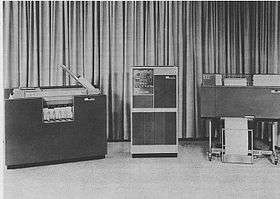
The IBM 1401 is a variable wordlength decimal computer that was announced by IBM on October 5, 1959. The first member of the highly successful IBM 1400 series, it was aimed at replacing unit record equipment for processing data stored on punched cards and at providing peripheral services for larger computers.[1] The 1401 is considered to be the Model-T Ford of the computer industry, because it was mass-produced and because of its sales volume. Over 12,000 units were produced and many were leased or resold after they were replaced with newer technology. The 1401 was withdrawn on February 8, 1971.
History
The 1401 project evolved from an IBM project named World Wide Accounting Machine (WWAM), which in turn was a reaction to the success of Bull Gamma 3.[2]
The 1401 was operated as an independent system, in conjunction with IBM punched card equipment, or as auxiliary equipment to IBM 700 or 7000 series systems.[3]
Monthly rental for 1401 configurations started at US$2,500 (worth about $20,987 today).[4]
"IBM was pleasantly surprised (perhaps shocked) to receive 5,200 orders in just the first five weeks – more than predicted for the entire life of the machine!"[5] By late 1961, the 2000 installed in the USA were about one quarter of all electronic stored-program computers by all manufacturers. The number of installed 1401s peaked above 10,000 in the mid-1960s. "In all, by the mid-1960s nearly half of all computer systems in the world were 1401-type systems."[5] The system was marketed until February 1971.[6]
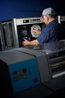
Commonly used by small businesses as their primary data processing machines, the 1401 was also frequently used as an off-line peripheral controller for mainframe computers. In such installations, with an IBM 7090 for example, the mainframe computers used only magnetic tape for input-output. It was the 1401 that transferred input data from slow peripherals (such as the IBM 1402 Card Read-Punch) to tape, and transferred output data from tape to the card punch, the IBM 1403 Printer, or other peripherals. This allowed the mainframe's throughput to not be limited by the speed of a card reader or printer. (For more information, see Spooling.)
Elements within IBM, notably John Haanstra, an executive in charge of 1401 deployment, supported its continuation in larger models for evolving needs (e.g., the IBM 1410) but the 1964 decision at the top to focus resources on the System/360 ended these efforts rather suddenly. Then, faced with the competitive threat of the Honeywell 200[7] and the 360's incompatibility with the 1401 design, IBM pioneered the use of microcode emulation, in the form of ROM, so that some System/360 models could run 1401 programs.[8]

During the 1970s, IBM installed many 1401s in India and Pakistan where they were in use well into the 1980s. Some of today's Indian and Pakistani software entrepreneurs started on these 1401s. The first computer in Pakistan, for example, was a 1401 installed at Pakistan International Airlines.[9]
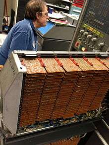
Two 1401 systems have been restored to operating order at the Computer History Museum in Mountain View, California, complete with a raised floor typical of the mainframe era (and modern data centers), used to hide cabling and distribute cooled air.[10][11]
Architecture

Each alphanumeric character in the 1401 was encoded by six bits, called B,A,8,4,2,1. The B,A bits were called zone bits and the 8,4,2,1 bits were called numeric bits, terms taken from the IBM 80 column punched card.
- For digits 1 through 9, the bits B,A were zero, the digit BCD encoded in bits 8,4,2,1. Digit 0 was encoded 8,2.
- For alphabetic characters the setting of bits was derived from the zone and digit punches of the IBM 80 column punched card character code: B,A from 12, B from 11, and A from 0; the setting of bits 8,4,2,1 from BCD encoding of the 1 through 9 punches. Thus the letter A, 12,1 in the punched card character code, was encoded B,A,1.
- Encodings of punched card characters with two or more digit punches can be found in the Character and op codes table.
IBM called the 1401's character code BCD, even though that term describes only the decimal digit encoding.[12] The 1401's alphanumeric collating sequence was compatible with the punched card collating sequence.
Associated with each memory location were two other bits, called C for odd parity check and M for word mark.
Each memory location then, had the following bits:
C B A 8 4 2 1 M
The 1401 was available in six memory configurations: 1400, 2000, 4000, 8000, 12000, or 16000 characters.[lower-alpha 1] Each character was addressable, addresses ranging from 0 through 15999. A very small number of 1401s were expanded to 32,000 characters by special request.
Some operations used specific memory locations (those locations were not reserved and could be used for other purposes). Read a card stored the 80 columns of data from a card into memory locations 001-080. Index registers 1, 2 and 3 were in memory locations 087-089, 092-094 and 097-099 respectively. Punch a card punched the contents of memory locations 101-180 into a card. Write a line printed the contents of memory locations 201-332.
The 1401's instruction format was
  Opcode
   with   [A-or-I-or-unit-address [B-address]] [modifier]
 word mark
Opcodes were one character. Memory addresses ("I" a branch target, "A" and "B" data) and unit address were three characters. The opcode modifier was one character. Instruction length was then 1, 2, 4, 5, 7, or 8 characters. Most instructions had to be followed by a word mark (a requirement commonly met by the word mark with the opcode of the next instruction).
See Character and op codes for a list of operations.
A three character memory address in an instruction was an encoding of a five digit memory address. The three low order digits of the five digit address, 000 to 999, were specified by the numeric bits of the three characters. The zone bits of the high-order character specified an increment as follows: A 1000, B 2000, B and A together 3000, giving an addressability of 4,000 memory locations. The zone bits of the low-order character specified increments of 4000, 8000, or 12000, to address 16,000 memory locations (with an IBM 1406 Storage Unit).[lower-alpha 2] For example, the three character address "I99" was a reference to memory location 3000 + 999, or 3999.
The zone bits of the middle character of a three character memory address could specify one of three index registers, one of many optional features.
Operands referenced by the A-address and B-address were: a single memory location, a variable length field, or a variable length record. Variable length fields were addressed at their low-order (highest-addressed) position, their length defined by a word mark set at their high-order (lowest-addressed) position. When an operation such as addition was performed, the processor began at the low-order position of the two fields and worked its way to the high-order, just as a person would when adding with pencil and paper.
The only limit on the length of such fields was the available memory. Instructions applicable to variable length fields included: Add, Subtract, Multiply, Divide, Compare, Move Characters to A or B Word Mark, Move Characters and Edit. One or more adjacent variable length fields could make up a variable length record. A variable length record was addressed at its high-order position, its length defined by a group-mark character with a word mark or a record-mark character in its low-order position. The instruction Move Characters Record or Group Mark could be used to assemble a block of records. A variable length record, or block of records, to be written to magnetic tape was addressed at its high-order position, its length defined by a group-mark character with a word mark immediately following its low-order position.
A sequence of operations on adjacent fields could be "chained", using the addresses left in the address registers by the previous operation. For example, addition of adjacent data fields might be coded as "A 700,850", "A 695,845", "A 690,840". With chaining, this could be coded as "A 700,850", "A", "A" - omitting data address from the 2nd and 3rd instructions.[13]
Booting and sample program
When the LOAD button on the 1402 Card Read-Punch was pressed, a card was read into memory locations 001-080, a word mark was set in location 001, the word marks in locations 002-080 were cleared, and execution started with the instruction at location 001. That was always the dyadic Set Word Mark (it was the only instruction not requiring a following word mark) to set word marks for the two following instructions. Execution of instructions in the card deck continued, loading the program into memory, setting word marks, and then branching to the program's start address.
One-card programs could be written for various tasks. Commonly available were a one-card program to print the deck of cards following it, and another to duplicate a deck to the card punch. From Tom Van Vleck's web site[14] here is a one-card program which will print "HELLO WORLD". Pressing LOAD (above) begins execution at location 001 (the first ",").
,008015,022029,036043,050054,055062,063065,069080/333/M0792502F1.065HELLO WORLD
The program is:
- Set word marks (opcode "," operands 008 015)
- Set more word marks
- Clear storage - part of the print area 333-300 (opcode "/" operand 333)
- Clear storage - the rest of the print area 299-200 (opcode "/" using a chained address)
- Move "HELLO WORLD" to the print area (opcode "M", operands 079 and 250)
- Print a line (opcode "2")
- Eject the page in the printer (opcode "F" modifier "1")
- Halt (opcode "." operand 065 - a branch address, to this same halt command, if start is pressed)
Hardware implementation
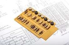
Most of the logic circuitry of the 1401 was a type of diode–transistor logic (DTL), that IBM referred to as CTDL (Complemented Transistor Diode Logic). Other IBM circuit types used were referred to as: Alloy (some logic, but mostly various non-logic functions, named for the germanium-alloy transistors used), CTRL (Complemented Transistor Resistor Logic, a type of resistor–transistor logic (RTL)). Later upgrades (e.g., the TAU-9 tape interface) used a faster type of DTL using "drift" transistors (a type of transistor invented by Herbert Kroemer in 1953) for their speed, that IBM referred to as SDTDL (Saturated Drift Transistor Diode Logic). Typical logic levels of these circuits were (S & U Level) high: 0 V to -0.5V, low: -6 V to -12 V; (T Level) high: 6 V to 1 V, low: -5.5 V to -6 V.
These circuits were constructed of discrete components (resistors, capacitors, transistors) mounted on single sided paper-epoxy printed circuit boards either 2.5 by 4.5 inches (64 by 114 mm) with a 16-pin gold plated edge connector (single wide) or 5.375 by 4.5 inches (136.5 by 114.3 mm) with two 16-pin gold plated edge connectors (double wide), that IBM referred to as SMS cards (Standard Modular System). The amount of logic on one card was similar to that in one 7400 series SSI or simpler MSI package (e.g., 3 to 5 logic gates or a couple of flip-flops on a single wide card up to about 20 logic gates or 4 flip-flops on a double wide card).
The SMS cards were inserted in sockets on hinged swing out racks, that IBM referred to as gates.
The modules used were fairly delicate, compared to previous unit-record equipment, so IBM shipped them enclosed in a newly invented packing material, bubble wrap. This was one of the first widespread uses of this packing; it greatly impressed recipients, and brought great publicity to the material.
Like most machines of the day, the 1401 used magnetic-core memory. The cores were about 1 mm in diameter and used a four-wire arrangement (x, y, sense, and inhibit). The memory was arranged in planes of 4000 cores each, each core storing one bit. A stack of eight such planes stored the six data bits, word mark bit, and parity bit for 4000 memory locations. Together with eight additional planes with fewer cores on them for additional storage functions, this made up a 4000-character memory module.[15] One such module could be housed within the 1401's primary enclosure. Systems were commonly available with two, three, or four such modules. The additional modules were contained in an add-on box, the 1406 Core Memory Unit, which was about two feet square and three high.
Operands in memory were accessed serially, one memory location at a time, and the 1401 could read or write one memory location within its basic cycle time of 11.5 microseconds.[16] All instruction timings were cited in multiples of this cycle time.[17]
IBM 1403 printer

The IBM 1403 printer was introduced in October 1959 with the 1401 Data Processing System. The printer was a completely new development.
Software
IBM software for the 1401 included:
- 1401 Symbolic Programming System assembler.
- Autocoder on Tape, a more advanced assembler, required at least 4000-character memory and four tape drives.
- Autocoder on Disk, similar to, but not compatible with, Autocoder on Tape, required at least one 1311 disk drive.
- COBOL required at least 4000-character memory and four tape drives.
- FARGO (Fourteen-o-one Automatic Report Generation Operation), a predecessor of RPG, required at least 4000-character memory.
- FORTRAN II required at least 8000-character memory; the 1401 Fortran compiler is described in Haines, L.H. (1965), below. The Fortran compiler, to generate code for small memories, used a pioneering form of interpreted "p-code" although its programmers had no name for what it was that they did.
- FORTRAN IV required at least 12000-character memory and either four tape drives or at least one IBM 1311 disk drive.
- RPG (Report Program Generator); Basic RPG required at least 4000-character memory.
For the IBM Catalog of 1401 software, see IBM 1400 series.
Character and op codes
The 1401's operation codes were single characters. In many cases, particularly for the more common instructions, the character chosen was mnemonic for the operation: A for add, B for branch, S for subtract, etc.
The table is in Character Collating Sequence.
- Note: If Word mark bit is set, then the C bit will be opposite of shown. The C bit was determined and checked automatically by the machine - normally it was of no concern to the programmers. The only way the C bit could be entered was by manually using the switches on the Auxiliary Console. A programmer might use these switches to make quick patches while debugging.
| BCD Character | Print-A | Print-H | Card | BCD
w/o M |
Operation | Definition & Notes |
|---|---|---|---|---|---|---|
| Blank | C | |||||
| . | . | . | 12-3-8 | BA8 21 | Halt | |
| ¤ | ¤ | ) | 12-4-8 | CBA84 | Clear Word Mark | Lozenge |
| [ | 12-5-8 | BA84 1 | ||||
| < | 12-6-8 | BA842 | Less Than | |||
| 12-7-8 | CBA8421 | Group Mark | ||||
| & | & | + | 12 | CBA | ||
| $ | $ | $ | 11-3-8 | CB 8 21 | ||
| * | * | * | 11-4-8 | B 84 | ||
| ] | 11-5-8 | CB 84 1 | ||||
| ; | 11-6-8 | CB 842 | ||||
| Δ | 11-7-8 | B 8421 | Delta (Mode Change) | |||
| - | - | - | 11 | B | ||
| / | / | / | 0-1 | C A 1 | Clear Storage | |
| , | , | , | 0-3-8 | C A8 21 | Set Word Mark | |
| % | % | ( | 0-4-8 | A84 | Divide | Optional special feature. |
| ˠ | 0-5-8 | C A84 1 | Word Separator | |||
| \ | 0-6-8 | C A842 | Left Oblique | |||
| ⧻ | 0-7-8 | A8421 | Tape Segment Mark | |||
| ƀ | ‡ | ‡ | N/A
0 |
A | Cannot be read from card without a no-cost RPQ, in which case it is read as 8-2.[lower-alpha 3]
Punches as zero (or 8-2 with the RPQ). Blank with "even-parity" on tape. | |
| # | # | = | 3-8 | 8 21 | Modify Address | Optional (requires more than
4000 characters of memory) |
| @ | @ | ' | 4-8 | C 84 | Multiply | Optional special feature. |
| : | 5-8 | 84 1 | ||||
| > | 6-8 | 842 | Greater Than | |||
| √ | 7-8 | C 8421 | Tape Mark | |||
| ? | & | & | 12-0 | CBA8 2 | Zero and Add | Plus Zero |
| A | A | A | 12-1 | BA 1 | Add | |
| B | B | B | 12-2 | BA 2 | Branch or Branch on Indicator | See "Modifiers for five-character Branch on Indicator (B) instruction" section |
| C | C | C | 12-3 | CBA 21 | Compare | |
| D | D | D | 12-4 | BA 4 | Move Numerical | (Bits) |
| E | E | E | 12-5 | CBA 4 1 | Move Characters and Edit | |
| F | F | F | 12-6 | CBA 42 | Control Carriage | (Printer) |
| G | G | G | 12-7 | BA 421 | ||
| H | H | H | 12-8 | BA8 | Store B-Address Register | Optional special feature. |
| I | I | I | 12-9 | CBA8 1 | ||
| ! | - | - | 11-0 | B 8 2 | Zero and Subtract | Minus Zero |
| J | J | J | 11-1 | CB 1 | ||
| K | K | K | 11-2 | CB 2 | Select Stacker and other device controls | See "Modifiers for Select Stacker (K) instruction" section |
| L | L | L | 11-3 | B 21 | Load Characters to Word Mark | |
| M | M | M | 11-4 | CB 4 | Move Characters to Word Mark | |
| N | N | N | 11-5 | B 4 1 | No Operation | |
| O | O | O | 11-6 | B 42 | ||
| P | P | P | 11-7 | CB 421 | Move Characters to
Record or Group Mark |
Optional special feature. |
| Q | Q | Q | 11-8 | CB 8 | Store A-Address Register | Optional special feature. |
| R | R | R | 11-9 | B 8 1 | ||
| ‡ | ‡ | ‡ | 0-2-8 | A8 2 | Record Mark | |
| S | S | S | 0-2 | C A 2 | Subtract | |
| T | T | T | 0-3 | A 21 | Translate | (1460 only) |
| U | U | U | 0-4 | C A 4 | Control Unit | (Tape) |
| V | V | V | 0-5 | A 4 1 | Branch if Word Mark
and/or Zone |
|
| W | W | W | 0-6 | A 42 | Branch if Bit Equal | Optional special feature. |
| X | X | X | 0-7 | C A 421 | Move and Insert Zeros | Optional special feature. |
| Y | Y | Y | 0-8 | C A8 | Move Zone | (Bits) |
| Z | Z | Z | 0-9 | A8 1 | Move Characters and
Suppress Zeros |
|
| 0 | 0 | 0 | 0 | C 8 2 | ||
| 1 | 1 | 1 | 1 | 1 | Read a Card | |
| 2 | 2 | 2 | 2 | 2 | Write a Line | |
| 3 | 3 | 3 | 3 | C 21 | Write and Read | |
| 4 | 4 | 4 | 4 | 4 | Punch a Card | |
| 5 | 5 | 5 | 5 | C 4 1 | Read and Punch | |
| 6 | 6 | 6 | 6 | C 42 | Write and Punch | |
| 7 | 7 | 7 | 7 | 421 | Write, Read, and Punch | |
| 8 | 8 | 8 | 8 | 8 | Start Read Feed | Optional special feature. |
| 9 | 9 | 9 | 9 | C 8 1 | Start Punch Feed | Optional special feature. |
Two of the instructions, Branch on Indicator (B) and Select Stacker (K), use a "modifier" operand.
Modifiers for five-character Branch on Indicator (B) instructionThe B opcode, if followed by a three-character operand, was a simple unconditional branch to the indicated address. If a fourth operand character was present (making five characters total including the opcode), this made it a conditional branch. This "modifier" character specified the condition to be tested.
|
Modifiers for Select Stacker (K) instructionThe Select Stacker (K) instruction sent commands to various devices. It was named for its relevance to the 1402 reader/punch.
|
1401 culture
In October 2006, Icelandic avant-garde musician Jóhann Jóhannsson released the album IBM 1401, A User's Manual through music publisher 4AD.[19] The concept is based upon work done in 1964 by his father, Jóhann Gunnarsson, chief maintenance engineer of one of the country's first computers, and Elías Daviðsson,[20] one of the first programmers in the country. The album was originally written for a string quartet, organ and electronics and to accompany a dance piece by long-standing collaborator friend, Erna Ómarsdóttir. For the album recording, Jóhann has rewritten it for a sixty-piece string orchestra, adding a new final movement and incorporating electronics and vintage reel-to-reel recordings of a singing 1401 found in his father's attic.[20]
More well-known were various demo programs to play music on transistor radios placed on the CPU[21] and computer "art", mostly kitschy pictures printed using Xs and 0s on chain printers.[22]
See also
Notes
- ↑ The 1401 was a decimal computer, so e.g. "8000" characters is not 8,192 characters.
- ↑ More simply stated: the four zone bits encoded the decimal values 0 to 15 as the binary numbers 0000 to 1111. The encoded value was used as the thousands part of a 1401 address. Thus making the 1401 a curious machine with memory addresses stored as a combination of 3 decimal digits and 4 binary digits. IBM did not use the word "binary" in describing the 1401's addressing (see the 1401 Reference Manual).
- ↑ The RPQ "Reader/Punch Card Code 8-2 and A-Bit Compatibility" (898148) causes the 1401 to read/punch the A bit as 8-2 for compatibility with the IBM 1410.[18]
References
- ↑ Boshe, Charles J.; Johnson, Lyle R.; Palmer, John H.; Pugh, Emerson W. (1986). IBM's Early Computers. MIT Press. p. 473.
... configured for stand-alone use as well as peripheral service for larger computers ... A small configuration, without tapes and with the minimum memory capacity, was available for just under $2500 per month, a much lower rental for much higher performance than three 407 accounting machines plus a 604 calculator.
- ↑ Information Technology Industry TimeLine Retrieved October 26, 2017.
- ↑ "1401 Data Processing System". IBM Archives. October 5, 1959. Retrieved June 2, 2010.
- ↑ Columbia University, Computing History Project
- 1 2 Spicer, Dag. "Back to Life: The story behind CHM's IBM 1401 Restoration" (PDF). Computer History Museum. Archived from the original (PDF) on November 5, 2010. Retrieved May 27, 2011.
- ↑ "FAQ's for Products and Services". IBM Archives. Retrieved June 2, 2010.
- ↑ among other things, Honeywell used the name Easycoder, resembling IBM's Autocoder.
- ↑ Pugh, Emerson W. (1995). Building IBM: Shaping an Industry and Its Technology. MIT. p. 273. ISBN 0-262-16147-8.
- ↑ "History of PIA".
- ↑ "1401 Restoration Project".
- ↑ "1401 "Rebuilding the IBM," by Philip E. Ross, IEEE Spectrum, November 2009".
- ↑ IBM and BCD
- ↑ IBM (April 1962). IBM 1401 Data Processing System: Reference Manual (PDF). p. 20. A24-1403-5. Archived from the original (PDF) on August 9, 2010.
- ↑ "Tom Van Vleck: 1401s I have known".
- ↑ Rob Storey. "Core memory frame from a 1401". Retrieved July 15, 2012.
- ↑ "The IBM 1401". IBM 1401 Restoration Project. Computer History Museum. Retrieved July 15, 2012.
The 1401’s clock frequency is 86,957 cycles per second, or about 87 kiloHertz! This corresponds to an 11.5 micro-second system clock cycle time. ... The 1401 CPU does everything in a character-serial manner. In order to add say two N-digit numbers, the CPU takes several cycles to fetch the instruction itself and then one cycle for every character of the instruction’s two operands or arguments, or 2N cycles total.
- ↑ IBM Corporation (1961). "IBM 1401 Principles of Programming, Section 7" (PDF). IBM Personal Study Program. IBM Corporation. p. 19. Retrieved July 15, 2012.
The timing of the IBM 1401 is described in terms of the time required for one complete core storage cycle, which is 11.5 microseconds ... The time required for any internal processing instruction is always a multiple of this interval of time.
- ↑ "Custom Features for IBM 1401, 1440, and 1460 Data Processing Systems" (PDF). Archived from the original (PDF) on August 29, 2012. Retrieved September 23, 2015.
- ↑ "IBM 1401, A User's Manual-Live in Italy". Retrieved January 29, 2015.
- 1 2 "Jóhann Jóhannsson: IBM 1401, A User's Manual". work's web site. Retrieved January 29, 2015.
- ↑ "1401-music-Movie".
- ↑ Gansing, Kristoffer (2007). "Working Paper version - Humans Thinking Like Machines - Incidental Media Art in the Swedish Welfare State" (PDF). University of Malmö, School of Arts & Communication. Retrieved 29 November 2017. A full version to be published in Place Studies in Art, Media, Science and Technology, VDG Weimar 2009
Videos
- IBM 1401 System - 50th Anniversary in the Computer History Museum YouTube November 19, 2009
- IBM 1401 French Presentation with English Subtitles YouTube April 20, 2014
- IBM 1401 for the Roper Corporation YouTube May 14, 2015
- The IBM 1401 compiles and runs FORTRAN II YouTube February 2, 2018
Further reading
- Bashe, Charles J.; Johnson, Lyle R; Palmer, John H.; Pugh, Emerson W. (1986). IBM's Early Computers. MIT. p. 717. ISBN 0-262-02225-7. Chapter 12 Broadening the Base pages 465-494, a history of IBM's 1401 and 1403 development
- IBM (April 1966). IBM 1401 System Summary (PDF). A24-1401-1. Brief descriptions of the machine features, components, configurations, and special features
- IBM (April 1962). IBM 1401 Data Processing System: Reference Manual (PDF). A24-1403-5. Archived from the original (PDF) on August 9, 2010.
External links
- 1401 documents on bitsavers.org
- A Century of Smart: The IBM 1401 (1959). IBM Social Media. November 16, 2009. Retrieved November 17, 2009. Video captures thoughts and reflections of some of the original 1401 team members from a reunion held in Endicott, NY in 2009. Includes footage from 1401 marketing films.
- 1401 videos and sounds
- 1401s I have Known, Tom Van Vleck
- Haines, L. H. (1965). "Serial compilation and the 1401 FORTRAN compiler". IBM Systems Journal. 4 (1): 73–80. doi:10.1147/sj.41.0073. This article was reprinted, edited, in both editions of Lee, John A. N. (1967). Anatomy of a Compiler (1st and 1974 2nd ed.). Van Nostrand Reinhold.
- Music inspired by the 1401: Johann Johannsson's "IBM 1401: A User's Manual" - CD / LP
- a double width SMS card used in the 1401 used germanium alloy transistors