Diode–transistor logic
Diode–transistor logic (DTL) is a class of digital circuits that is the direct ancestor of transistor–transistor logic. It is called so because the logic gating function (e.g., AND) is performed by a diode network and the amplifying function is performed by a transistor (in contrast with RTL and TTL).
Implementations
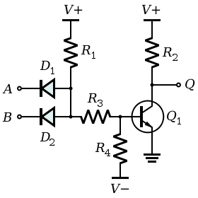
The DTL circuit shown in the picture consists of three stages: an input diode logic stage (D1, D2 and R1), an intermediate level shifting stage (R3 and R4), and an output common-emitter amplifier stage (Q1 and R2). If both inputs A and B are high (logic 1; near V+), then the diodes D1 and D2 are reverse biased. Resistors R1 and R3 will then supply enough current to turn on Q1 (drive Q1 into saturation) and also supply the current needed by R4. There will be a small positive voltage on the base of Q1 (VBE, about 0.3 V for germanium and 0.6 V for silicon). The turned on transistor's collector current will then pull the output Q low (logic 0; VCE(sat), usually less than 1 volt). If either or both inputs are low, then at least one of the input diodes conducts and pulls the voltage at the anodes to a value less than about 2 volts. R3 and R4 then act as a voltage divider that makes Q1's base voltage negative and consequently turns off Q1. Q1's collector current will be essentially zero, so R2 will pull the output voltage Q high (logic 1; near V+).
Discrete
The IBM 1401 (announced in 1959[1]) used DTL circuits similar to the circuit shown in the picture.[2] IBM called the logic "complemented transistor diode logic" (CTDL).[3] CTDL avoided the level shifting stage (R3 and R4) by alternating NPN and PNP based gates operating on different power supply voltages. The 1401 used germanium transistors and diodes in its basic gates.[4] The 1401 also added an inductor in series with R2.[4][5] The physical packaging used the IBM Standard Modular System.
Integrated
In an integrated circuit version of the DTL gate, R3 is replaced by two level-shifting diodes connected in series. Also the bottom of R4 is connected to ground to provide bias current for the diodes and a discharge path for the transistor base. The resulting integrated circuit runs off a single power supply voltage.[6][7][8]
In 1962, Signectics introduced the SE100-series family, the first high-volume DTL chips. In 1964, Fairchild released the 930-series DTµL micrologic family that had a better noise immunity, smaller die, and lower cost. It was the most commercial successful DTL family and copied by other IC manufacturers.[9][10]
Speed improvement
The DTL propagation delay is relatively large. When the transistor goes into saturation from all inputs being high, charge is stored in the base region. When it comes out of saturation (one input goes low) this charge has to be removed and will dominate the propagation time.
One way to speed up DTL is to add a small "speed-up" capacitor across R3. The capacitor helps to turn off the transistor by removing the stored base charge; the capacitor also helps to turn on the transistor by increasing the initial base drive.[11]
Another way to speed up DTL is to avoid saturating the switching transistor. That can be done with a Baker clamp. The Baker clamp is named for Richard H. Baker, who described it in his 1956 technical report "Maximum Efficiency Switching Circuits."[12]
In 1964, James R. Biard filed a patent for the Schottky transistor.[13] In his patent the Schottky diode prevented the transistor from saturating by minimizing the forward bias on the collector-base transistor junction, thus reducing the minority carrier injection to a negligible amount. The diode could also be integrated on the same die, it had a compact layout, it had no minority carrier charge storage, and it was faster than a conventional junction diode. His patent also showed how the Schottky transistor could be used in DTL circuits and improve the switching speed of other saturated logic designs, such as Schottky-TTL, at a low cost.
Interfacing considerations
A major advantage over the earlier resistor–transistor logic is increased fan-in. Additionally, to increase fan-out, an additional transistor and diode may be used.[14]
See also
References
- ↑ computermuseum.li
- ↑ The IBM 1401 may have also used a current mode logic.
- ↑ IBM 1960, p. 6
- 1 2 IBM 1401 logic Archived 2010-08-09 at the Wayback Machine. Retrieved on 2009-06-28.
- ↑ IBM (1960). Customer Engineering Manual of Instruction: Transistor Component Circuits (PDF). IBM. Form 223-688 (5M-11R-156). Retrieved 2012-04-24.
- ↑ Delham, Louis A. (1968), Design and Application of Transistor Switching Circuits, Texas Instruments Electronics Series, McGraw-Hill , page 188 states resistor is replaced with one or more diodes; figure 10-43 shows 2 diodes; cites to Schulz 1962.
- ↑ Schulz, D. (August 1962), "A High Speed Diode Coupled NOR Gate", Solid State Design, 1 (8): 52, OCLC 11579670
- ↑ ASIC world: "Diode Transistor Logic"
- ↑ 1963: Standard Logic IC Families Introduced; Comuter History Museum.
- ↑ Monolithic integrated circuit history; Andrew Wylie.
- ↑ Roehr, William D., ed. (1963), High-Speed Switching Transistor Handbook, Motorola, Inc. . Page 32 states: "As the input signal changes, the charge on the capacitor is forced into the base of the transistor. This charge can effectively cancel the transistor stored charge, resulting in a reduction of storage time. This method is very effective if the output impedance of the preceding stage is low so that the peak reverse current into the transistor is high."
- ↑ Baker, R. H. (1956), "Maximum Efficiency Switching Circuits", MIT Lincoln Laboratory Report TR-110
- ↑
- US 3463975, Biard, James R., "Unitary Semiconductor High Speed Switching Device Utilizing a Barrier Diode", published December 31, 1964, issued August 26, 1969
- ↑ Jacob Millman, (1979). Microelectronics Digital and Analog Circuits and Systems. New York: McGraw-Hill Book Company. pp. 141–143. ISBN 0-07-042327-X.
Further reading
- Design and Application of Transistor Switch Circuits; Louis A. Delhom; Texas Instruments and McGraw-Hill; 278 pages; 1968; LCCCN 67-22955. (see chapter 10.7)
- 1964 Fairchild DTµL Micrologic Catalog; 36 pages. (see catalog)
- 1965 Fairchild Catalog; 49 pages. (see pages 33 to 34)
- 1975 Fairchild Full Line Condensed Catalog; 354 pages. (see pages 2-129 to 2-130)
- 1978 Fairchild Full Line Condensed Catalog; 530 pages. (see pages 13-110 to 13-113)
External links
- Savard, John J. G. (2018) [2005]. "What Computers Are Made From". quadibloc. Archived from the original on 2018-07-02. Retrieved 2018-07-16.
- Diode-Transistor Logic (slides) - University of Connecticut
- Diode-Transistor Logic - University of Babylon