Control loop
A control loop is the fundamental building block of industrial control systems. It consists of all the physical components and control functions necessary to automatically adjust the value of a measured process variable (PV) to equal the value of a desired set-point (SP). It includes the process sensor, the controller function, and the final control element (FCE) which are all required for automatic control.
Application
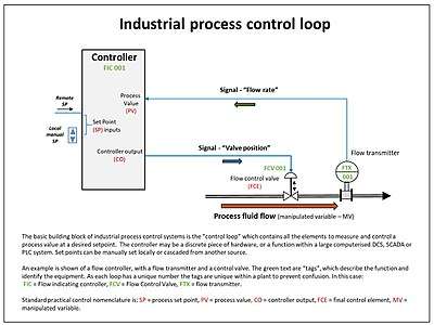
The accompanying diagram shows a control loop with a single PV input, a control function, and the control output (CO) which modulates the action of the final control element (FCE) to alter the value of the manipulated variable (MV). In this example, a flow control loop is shown, but can be level, temperature, or any one of many process parameters which need to be controlled. The control function shown is an "intermediate type" such as a PID controller which means it can generate a full range of output signals anywhere between 0-100%, rather than just an on/off signal. [1]
In this example the value of the PV is always the same as the MV, as they are in series in the pipeline. However, if the feed from the valve was to a tank, and the controller function was to control level using the fill valve, the PV would be the tank level, and the MV would be the flow to the tank.
The controller function can be a discrete controller, or a function block in a computerised control system such as a distributed control system or a programmable logic controller. In all cases, a control loop diagram is a very convenient and useful way of representing the control function and its interaction with plant. In practice at a process control level, the control loops are normally abbreviated using standard symbols in a Piping and instrumentation diagram, which shows all elements of the process measurement and control based on a process flow diagram.[2]
At a detailed level the control loop connection diagram is created to show the electrical and pneumatic connections. This greatly aids diagnostics and repair, as all the connections for a single control function are on one diagram.
Loop and control equipment tagging
To aid unique identification of equipment, each loop and its elements are identified by a "tagging" system and each element has a unique tag identification.[3]
Based on the standards ANSI/ISA S5.1 and ISO 14617-6, the identifications consist of up to 5 letters.
The first identification letter is for the measured value, the second is a modifier, 3rd indicates passive/readout function, 4th - active/output function, and the 5th is the function modifier. This is followed by loop number, which is unique to that loop.
For instance FIC045 means it is the Flow Indicating Controller in control loop 045. This is also known as the "tag" identifier of the field device, which is normally given to the location and function of the instrument. The same loop may have FT045 - which is the flow transmitter in the same loop.
| Letter | Column 1 Measured value | Column 2 Modifier | Column 3 Readout/passive function | Column 4 Output/active function | Column 5 Function modifier |
| A | Analysis | Alarm | |||
| B | Burner, combustion | User choice | User choice | User choice | |
| C | User's choice - usually conductivity | Control | Close | ||
| D | User's choice - usually density | Difference | Deviation | ||
| E | Voltage | Sensor | |||
| F | Flow rate | Ratio | |||
| G | User's choice (usually gaging/gauging) | Gas | Glass/gauge/viewing | ||
| H | Hand | High | |||
| I | Current | Indicate | |||
| J | Power | Scan | |||
| K | Time, time schedule | Time rate of change | Control station | ||
| L | Level | Light | Low | ||
| M | User's choice | Middle / intermediate | |||
| N | User's choice (usually torque) | User choice | User choice | User choice | |
| O | User's choice | Orifice | Open | ||
| P | Pressure | Point/test connection | |||
| Q | Quantity | Totalize/integrate | Totalize/integrate | ||
| R | Radiation | Record | Run | ||
| S | Speed, frequency | Switch | Stop | ||
| T | Temperature | Transmit | |||
| U | Multivariable | Multifunction | Multifunction | ||
| V | Vibration, mechanical analysis | Valve or damper | |||
| W | Weight, force | Well or probe | |||
| X | User's choice - usually on-off valve as XV | X-axis | Accessory devices, unclassified | Unclassified | Unclassified |
| Y | Event, state, presence | Y-axis | Auxiliary devices | ||
| Z | Position, dimension | Z-axis or Safety | Actuator, driver or unclassified final control element | ||
For reference designation of any equipment in industrial systems the standard IEC 61346 (Industrial systems, installations and equipment and industrial products — Structuring principles and reference
References
- ↑ Cooper, Douglas. "Control Guru". Control Guru terminology. Retrieved 16 September 2017.
- ↑ "Piping and instrumentation diagram P&ID". Process Flow Systems. Retrieved 16 September 2017.
- ↑ "Components of control loops and ISA symbology" (PDF). Instrumentation and control - process control fundamentals. Retrieved 16 September 2017.