Chroma subsampling
Chroma subsampling is the practice of encoding images by implementing less resolution for chroma information than for luma information, taking advantage of the human visual system's lower acuity for color differences than for luminance.[1]
It is used in many video encoding schemes – both analog and digital – and also in JPEG encoding.
Rationale
Digital signals are often compressed to reduce file size and save transmission time. Since the human visual system is much more sensitive to variations in brightness than color, a video system can be optimized by devoting more bandwidth to the luma component (usually denoted Y'), than to the color difference components Cb and Cr. In compressed images, for example, the 4:2:2 Y'CbCr scheme requires two-thirds the bandwidth of (4:4:4) R'G'B'. This reduction results in almost no visual difference as perceived by the viewer.
How subsampling works
Because the human visual system is less sensitive to the position and motion of color than luminance,[2] bandwidth can be optimized by storing more luminance detail than color detail. At normal viewing distances, there is no perceptible loss incurred by sampling the color detail at a lower rate. In video systems, this is achieved through the use of color difference components. The signal is divided into a luma (Y') component and two color difference components (chroma).
In human vision there are three channels for color detection, and for many color systems, three "channels" is sufficient for representing most colors. For example: red, green, blue or magenta, yellow, cyan. But there are other ways to represent the color. In many video systems, the three channels are luminance and two chroma channels. In video, the luma and chroma components are formed as a weighted sum of gamma-corrected (tristimulus) R'G'B' components instead of linear (tristimulus) RGB components. As a result, luma must be distinguished from luminance. That there is some "bleeding" of luminance and color information between the luma and chroma components in video, the error being greatest for highly saturated colors and noticeable in between the magenta and green bars of a color-bar test pattern (that has chroma subsampling applied), should not be attributed to this engineering approximation being used. Indeed, similar bleeding can occur also with gamma = 1, whence the reversing of the order of operations between gamma correction and forming the weighted sum can make no difference. The chroma can influence the luma specifically at the pixels where the subsampling put no chroma. Interpolation may then put chroma values there which are incompatible with the luma value there, and further post-processing of that Y'CbCr into R'G'B' for that pixel is what ultimately produces false luminance upon display.

Original without color subsampling. 200% zoom.

Image after color subsampling (compressed with Sony Vegas DV codec, box filtering applied.)
Sampling systems and ratios
The subsampling scheme is commonly expressed as a three part ratio J:a:b (e.g. 4:2:2) or four parts if alpha channel is present (e.g. 4:2:2:4), that describe the number of luminance and chrominance samples in a conceptual region that is J pixels wide, and 2 pixels high. The parts are (in their respective order):
- J: horizontal sampling reference (width of the conceptual region). Usually, 4.
- a: number of chrominance samples (Cr, Cb) in the first row of J pixels.
- b: number of changes of chrominance samples (Cr, Cb) between first and second row of J pixels.
- Alpha: horizontal factor (relative to first digit). May be omitted if alpha component is not present, and is equal to J when present.
This notation is not valid for all combinations and has exceptions, e.g. 4:1:0 (where the height of the region is not 2 pixels but 4 pixels, so if 8 bits/component are used the media would be 9 bits/pixel) and 4:2:1.
An explanatory image of different chroma subsampling schemes can be seen at the following link: http://lea.hamradio.si/~s51kq/subsample.gif (source: "Basics of Video": http://lea.hamradio.si/~s51kq/V-BAS.HTM) or in details in Chrominance Subsampling in Digital Images, by Douglas Kerr.
| 4:1:1 | 4:2:0 | 4:2:2 | 4:4:4 | 4:4:0 | ||||||||||||||||||||||||||
| Y'CrCb | ||||||||||||||||||||||||||||||
| = | = | = | = | = | ||||||||||||||||||||||||||
| Y' | ||||||||||||||||||||||||||||||
| + | + | + | + | + | ||||||||||||||||||||||||||
| 1 | 2 | 3 | 4 | J = 4 | 1 | 2 | 3 | 4 | J = 4 | 1 | 2 | 3 | 4 | J = 4 | 1 | 2 | 3 | 4 | J = 4 | 1 | 2 | 3 | 4 | J = 4 | ||||||
| (Cr, Cb) | 1 | a = 1 | 1 | 2 | a = 2 | 1 | 2 | a = 2 | 1 | 2 | 3 | 4 | a = 4 | 1 | 2 | 3 | 4 | a = 4 | ||||||||||||
| 1 | b = 1 | b = 0 | 1 | 2 | b = 2 | 1 | 2 | 3 | 4 | b = 4 | b = 0 | |||||||||||||||||||
| ¼ horizontal resolution, full vertical resolution |
½ horizontal resolution, ½ vertical resolution |
½ horizontal resolution, full vertical resolution |
full horizontal resolution, full vertical resolution |
full horizontal resolution, ½ vertical resolution | ||||||||||||||||||||||||||
The mapping examples given are only theoretical and for illustration. Also note that the diagram does not indicate any chroma filtering, which should be applied to avoid aliasing.
To calculate required bandwidth factor relative to 4:4:4 (or 4:4:4:4), one needs to sum all the factors and divide the result by 12 (or 16, if alpha is present).
Types of sampling and subsampling
4:4:4
Each of the three Y'CbCr components have the same sample rate, thus there is no chroma subsampling. This scheme is sometimes used in high-end film scanners and cinematic post production.
Note that "4:4:4" may instead be referring to R'G'B' color space, which implicitly also does not have any chroma subsampling. Formats such as HDCAM SR can record 4:4:4 R'G'B' over dual-link HD-SDI.
4:2:2
The two chroma components are sampled at half the sample rate of luma: the horizontal chroma resolution is halved. This reduces the bandwidth of an uncompressed video signal by one-third with little to no visual difference.
Many high-end digital video formats and interfaces use this scheme:
- AVC-Intra 100
- Digital Betacam
- DVCPRO50 and DVCPRO HD
- Digital-S
- CCIR 601 / Serial Digital Interface / D1
- ProRes (HQ, 422, LT, and Proxy)
- XDCAM HD422
- Canon MXF HD422
4:2:1
This sampling mode is not expressible in J:a:b notation. '4:2:1' is an obsolete term from a previous notational scheme, and very few software or hardware codecs use it. Cb horizontal resolution is half that of Cr (and a quarter of the horizontal resolution of Y).
4:1:1
In 4:1:1 chroma subsampling, the horizontal color resolution is quartered, and the bandwidth is halved compared to no chroma subsampling. Initially, 4:1:1 chroma subsampling of the DV format was not considered to be broadcast quality and was only acceptable for low-end and consumer applications.[3][4] However, DV-based formats (some of which use 4:1:1 chroma subsampling) have been used professionally in electronic news gathering and in playout servers. DV has also been sporadically used in feature films and in digital cinematography.
In the NTSC system, if the luma is sampled at 13.5 MHz, then this means that the Cr and Cb signals will each be sampled at 3.375 MHz, which corresponds to a maximum Nyquist bandwidth of 1.6875 MHz, whereas traditional "high-end broadcast analog NTSC encoder" would have a Nyquist bandwidth of 1.5 MHz and 0.5 MHz for the I/Q channels. However, in most equipment, especially cheap TV sets and VHS/Betamax VCRs the chroma channels have only the 0.5 MHz bandwidth for both Cr and Cb (or equivalently for I/Q). Thus the DV system actually provides a superior color bandwidth compared to the best composite analog specifications for NTSC, despite having only 1/4 of the chroma bandwidth of a "full" digital signal.
Formats that use 4:1:1 chroma subsampling include:
4:2:0
In 4:2:0, the horizontal sampling is doubled compared to 4:1:1, but as the Cb and Cr channels are only sampled on each alternate line in this scheme, the vertical resolution is halved. The data rate is thus the same. This fits reasonably well with the PAL color encoding system since this has only half the vertical chrominance resolution of NTSC. It would also fit extremely well with the SECAM color encoding system since like that format, 4:2:0 only stores and transmits one color channel per line (the other channel being recovered from the previous line). However, little equipment has actually been produced that outputs a SECAM analogue video signal. In general SECAM territories either have to use a PAL capable display or a transcoder to convert the PAL signal to SECAM for display.
Different variants of 4:2:0 chroma configurations are found in:
- All ISO/IEC MPEG and ITU-T VCEG H.26x video coding standards including H.262/MPEG-2 Part 2 implementations (although some profiles of MPEG-4 Part 2 and H.264/MPEG-4 AVC allow higher-quality sampling schemes such as 4:4:4)
- DVD-Video and Blu-ray Disc.[5][6]
- PAL DV and DVCAM
- HDV
- AVCHD and AVC-Intra 50
- Apple Intermediate Codec
- most common JPEG/JFIF and MJPEG implementations
- VC-1
Cb and Cr are each subsampled at a factor of 2 both horizontally and vertically.
There are three variants of 4:2:0 schemes, having different horizontal and vertical siting.[7]
- In MPEG-2, Cb and Cr are cosited horizontally. Cb and Cr are sited between pixels in the vertical direction (sited interstitially).
- In JPEG/JFIF, H.261, and MPEG-1, Cb and Cr are sited interstitially, halfway between alternate luma samples.
- In 4:2:0 DV, Cb and Cr are co-sited in the horizontal direction. In the vertical direction, they are co-sited on alternating lines.
Most digital video formats corresponding to PAL use 4:2:0 chroma subsampling, with the exception of DVCPRO25, which uses 4:1:1 chroma subsampling. Both the 4:1:1 and 4:2:0 schemes halve the bandwidth compared to no chroma subsampling.
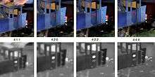
With interlaced material, 4:2:0 chroma subsampling can result in motion artifacts if it is implemented the same way as for progressive material. The luma samples are derived from separate time intervals while the chroma samples would be derived from both time intervals. It is this difference that can result in motion artifacts. The MPEG-2 standard allows for an alternate interlaced sampling scheme where 4:2:0 is applied to each field (not both fields at once). This solves the problem of motion artifacts, reduces the vertical chroma resolution by half, and can introduce comb-like artifacts in the image.

Original. *This image shows a single field. The moving text has some motion blur applied to it.

4:2:0 progressive sampling applied to moving interlaced material. Note that the chroma leads and trails the moving text. *This image shows a single field.

4:2:0 interlaced sampling applied to moving interlaced material. *This image shows a single field.
In the 4:2:0 interlaced scheme however, vertical resolution of the chroma is roughly halved since the chroma samples effectively describe an area 2 samples wide by 4 samples tall instead of 2X2. As well, the spatial displacement between both fields can result in the appearance of comb-like chroma artifacts.

Original still image.
4:2:0 progressive sampling applied to a still image. Both fields are shown.

4:2:0 interlaced sampling applied to a still image. Both fields are shown.
If the interlaced material is to be de-interlaced, the comb-like chroma artifacts (from 4:2:0 interlaced sampling) can be removed by blurring the chroma vertically.[8]
4:1:0
This ratio is possible, and some codecs support it, but it is not widely used. This ratio uses half of the vertical and one-fourth the horizontal color resolutions, with only one-eighth of the bandwidth of the maximum color resolutions used. Uncompressed video in this format with 8-bit quantization uses 10 bytes for every macropixel (which is 4 x 2 pixels). It has the equivalent chrominance bandwidth of a PAL I signal decoded with a delay line decoder, and still very much superior to NTSC.
- Some video codecs may operate at 4:1:0.5 or 4:1:0.25 as an option, so as to allow similar to VHS quality.
3:1:1
Used by Sony in their HDCAM High Definition recorders (not HDCAM SR). In the horizontal dimension, luma is sampled horizontally at three quarters of the full HD sampling rate – 1440 samples per row instead of 1920. Chroma is sampled at 480 samples per row, a third of the luma sampling rate.
In the vertical dimension, both luma and chroma are sampled at the full HD sampling rate (1080 samples vertically).
Out-of-gamut colors
One of the artifacts that can occur with chroma subsampling is that out-of-gamut colors can occur upon chroma reconstruction. Suppose the image consisted of alternating 1-pixel red and black lines and the subsampling omitted the chroma for the black pixels. Chroma from the red pixels will be reconstructed onto the black pixels, causing the new pixels to have positive red and negative green and blue values. As displays cannot output negative light (negative light does not exist), these negative values will effectively be clipped and the resulting luma value will be too high.[9] Similar artifacts arise in the less artificial example of gradation near a fairly sharp red/black boundary.
Filtering during subsampling can also cause colors to go out of gamut.
Terminology
The term Y'UV refers to an analog encoding scheme while Y'CbCr refers to a digital encoding scheme. One difference between the two is that the scale factors on the chroma components (U, V, Cb, and Cr) are different. However, the term YUV is often used erroneously to refer to Y'CbCr encoding. Hence, expressions like "4:2:2 YUV" always refer to 4:2:2 Y'CbCr since there simply is no such thing as 4:x:x in analog encoding (such as YUV).
In a similar vein, the term luminance and the symbol Y are often used erroneously to refer to luma, which is denoted with the symbol Y'. Note that the luma (Y') of video engineering deviates from the luminance (Y) of color science (as defined by CIE). Luma is formed as the weighted sum of gamma-corrected (tristimulus) RGB components. Luminance is formed as a weighed sum of linear (tristimulus) RGB components.
In practice, the CIE symbol Y is often incorrectly used to denote luma. In 1993, SMPTE adopted Engineering Guideline EG 28, clarifying the two terms. Note that the prime symbol ' is used to indicate gamma correction.
Similarly, the chroma/chrominance of video engineering differs from the chrominance of color science. The chroma/chrominance of video engineering is formed from weighted tristimulus components, not linear components. In video engineering practice, the terms chroma, chrominance, and saturation are often used interchangeably to refer to chrominance.
History
Chroma subsampling was developed in the 1950s by Alda Bedford for the development of color television by RCA, which developed into the NTSC standard; luma-chroma separation was developed earlier, in 1938 by Georges Valensi.
Through studies, he showed that the human eye has high resolution only for black and white, somewhat less for "mid-range" colors like yellows and greens, and much less for colors on the end of the spectrum, reds and blues. Using this knowledge allowed RCA to develop a system in which they discarded most of the blue signal after it comes from the camera, keeping most of the green and only some of the red; this is chroma subsampling in the YIQ color space, and is roughly analogous to 4:2:1 subsampling, in that it has decreasing resolution for luma, yellow/green, and red/blue.
See also
- Color space
- SMPTE - Society of Motion Picture and Television Engineers
- Digital video
- HDTV
- YCbCr
- YPbPr
- CCIR 601 4:2:2 SDTV
- YUV
- Color
- Color vision
- Better pictorial explanation here
References
- ↑ S. Winkler, C. J. van den Branden Lambrecht, and M. Kunt (2001). "Vision and Video: Models and Applications". In Christian J. van den Branden Lambrecht. Vision models and applications to image and video processing. Springer. p. 209. ISBN 978-0-7923-7422-0.
- ↑ Livingstone, Margaret (2002). "The First Stages of Processing Color and Luminance: Where and What". Vision and Art: The Biology of Seeing. New York: Harry N. Abrams. pp. 46–67. ISBN 0-8109-0406-3.
- ↑ Jennings, Roger; Bertel Schmitt (1997). "DV vs. Betacam SP". DV Central. Retrieved 2008-08-29.
- ↑ Wilt, Adam J. (2006). "DV, DVCAM & DVCPRO Formats". adamwilt.com. Retrieved 2008-08-29.
- ↑ Clint DeBoer (2008-04-16). "HDMI Enhanced Black Levels, xvYCC and RGB". Audioholics. Retrieved 2013-06-02.
- ↑ "Digital Color Coding" (PDF). Telairity. Retrieved 2013-06-02.
- ↑ Poynton, Charles (2008). "Chroma Subsampling Notation" (PDF). Poynton.com. Retrieved 2008-10-01.
- ↑ Munsil, Don; Stacey Spears (2003). "DVD Player Benchmark - Chroma Upsampling Error". Secrets of Home Theater and High Fidelity. Retrieved 2008-08-29.
- ↑ Chan, Glenn (May–June 2008). "Towards Better Chroma Subsampling". GlennChan.info. SMPTE Journal. Retrieved 2008-08-29.
- Poynton, Charles. "YUV and luminance considered harmful: A plea for precise terminology in video"
- Poynton, Charles. "Digital Video and HDTV: Algorithms and Interfaces". U.S.: Morgan Kaufmann Publishers, 2003.
- Kerr, Douglas A. "Chrominance Subsampling in Digital Images"
Data compression methods | |||||||
|---|---|---|---|---|---|---|---|
| Lossless |
| ||||||
| Audio |
| ||||||
| Image |
| ||||||
| Video |
| ||||||
| Theory | |||||||
| |||||||