Caribou Air Force Station
| Caribou Air Force Station | |
|---|---|
|
Part of Air Force Logistics Command Strategic Air Command | |
| Limestone, Maine | |
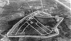 The station in 1967 | |
| Coordinates | 46°58′9.80″N 67°52′19.77″W / 46.9693889°N 67.8721583°WCoordinates: 46°58′9.80″N 67°52′19.77″W / 46.9693889°N 67.8721583°W |
| Site history | |
| Built | 1951 |
| Built by | U.S. Air Force |
| In use | 1951-1962 |
| Garrison information | |
| Garrison | Limestone, Maine |
Caribou Air Force Station, also known as North River Depot and East Loring, is a defunct Air Force Station that operated from 1951 until some time when it was absorbed into Loring Air Force Base in 1962. It was located in Limestone, Maine, adjacent to Loring. Between 1951 and 1962 Caribou was an Operational Storage Site for Air Materiel Command (AMC-OSS), one of five in the United States, and the weapons storage and maintenance facility for Loring alert aircraft.
Background
The Nuclear Weapons Storage Area at Loring once operated as a separate, top secret facility. Originally called the North River Depot, the remote area to the northeast of Loring’s property was the first U.S. Operational site allegedly constructed for the storage, assembly, and testing of atomic weapons.[1]
A parallel series of four fences, one of which was electrified, surrounded the heart of the storage area. This area was nicknamed the “Q” Area, which denoted the Department of Energy’s Q clearance a classified security clearance required to have access to Restricted Data.
In June 1962, the United States Atomic Energy Commission released its custody and ownership of the weapons to the Air Force, and the personnel and property were absorbed into the adjacent Loring Air Force Base.
Development and Structures
Caribou Air Force Station was the first of five, United States Air Force, Air Material Command (AMC) installations that were constructed during the period of 1951 – 1953. Each of the five installations was built specifically to provide operational storage of the nuclear stockpile, and to provide a specified number of weapons to their adjacent Strategic Air Command (SAC) bases. The first four installations were built and occupied by 1953. The fifth installation, although completed in 1953, would not be utilized until 1955. The first installation, code named “Site Easy” was originally known as the “North River Depot”. It was constructed between 1951-1952, and operations began in 1952. Funds were provided in 1951 to the Armed Forces Special Weapons Project (AFSWP), for the planning and construction of an ordnance storage site in the vicinity of a new Strategic Air Command Base. The AFSWP was directed to utilize the services of the Corps of Engineers, Department of Army, for planning and construction, and was made responsible for monitoring such work, and for operational security measures during these phases. The original directive to the AFSWP stipulated that upon completion of construction the installation would be turned over to Headquarters, Air Material Command for operational responsibilities.
By a contract with the Office of Chief of Engineers, the Black and Veatch firm of Kansas City, Missouri, was commissioned as Architects-Engineers for the planning of the project under the monitorship of the Midwest Engineer and Construction Office. This was a field agency responsible to the AFSWP and to the Chief of Engineers, and located at Kansas City, Missouri. During the planning phase, representatives of Headquarters, Air Material Command, made frequent visits to the Kansas City Office for consultation and familiarization purposes. The New England Engineer Division, U.S. Army Corps of Engineers, solicited bids, awarded construction contracts, and provided supervision of the construction. During construction the Midwest Office maintained a clearance agency at the site for the purpose of screening all workmen and other personnel on the project, and for facilitating various contractual functions. Contracts involving construction of certain (classified) facilities peculiar to the mission of the site were awarded, and work supervised directly by the Midwest Office of Kansas City, Missouri. Prior to the start of construction approximately 80% of the area was covered with forests of softwoods consisting of pine, hemlock, birch, and spruce trees. The exact location of Site Easy was on the east side of the neighboring SAC base and in the northern most section. Contractors started building a self-sufficient area on August 4, 1951. Designed as a maximum security storage area for the most advanced weapons of mankind, construction during 1951 and 1952 included a large living complex of barracks and recreational facilities, warehouse, offices, weapon maintenance areas and twenty-seven storage igloos. The area was a complete mini-base whose mission would be to protect and maintain the nuclear weapons deployed by the United States.
The buildings constructed at this site were identical to those constructed at the four other operational storage sites, although their layout and locations differed from site to site. In addition, Site Easy would become the largest of the original five operational storage sites. The installation was composed of two major zones: the Storage Zone or Q-Area, and the Administration Zone, in which were located the Administration Area and the Service Area. A chain link fence enclosed each of these areas. Access was gained by the main entrance gate of the Administration Zone, while the Q-Area was entered through another gate inside the fence system. Parking spaces were available in the Administration Area, and were distributed among the Administration Building, Bachelor Officers Quarters, Airmen’s Dormitories, Dining Hall, Warehouses and Shop Areas. Privately owned vehicles were not permitted to circulate in the Q-Area, and had to be parked outside of the gate. Parking spaces for such vehicles were provided in a paved, enclosed service yard east of the access road leading to the Q-Area gate. The roads at the site were all weather, with a hot-top surface, and an aggregate base course. Sidewalks were generally asphaltic concrete. The surfaced widths of roads varied. The main access road was twenty-two feet; The ordnance or Q-Area roads, and airstrip road were twenty feet; Service roads and roads on all four sides of the Administration Area were eighteen feet in width; and the patrol road was ten feet. One lane was provided for incoming traffic onto the station, and another for outgoing traffic. Each vehicle was required to stop and all personnel were required to undergo identification procedures. There were no traffic control lights on any road or street and traffic control by Air Police was necessary only during periods when heavy shipments of weapons were in movement to or from the Q-Area.
A spur track on Government-owned property and constructed at Government expense, extended from the adjacent SAC base over a distance of about four miles to the nearest town, where it connected with the main civilian railroad system. One of the secondary spurs, which branched off of the main spur between the SAC base and the nearby town, led to an unloading area, which was used only for the handling of weapons. This loading point was reached by the twenty-two foot wide asphalt paved highway which extended for a distance of approximately 3600 feet between the site entrance gate and the rail loading point. Building No. 400 was the Railhead Station. It was constructed of concrete block, and was razed sometime in the late 1980s. The overall Service Area, comprising the various functions of site maintenance and service, was strategically located in close proximity to the main entrance gate, and to the Administration and Storage Areas. The Service Area, situated southeast of the Administrative Area and outside of the maximum-security area, was the center of station maintenance, repair, and service. The Civil Engineering Division Area, or the former Installations Engineer Maintenance Area, was located near the Warehouse and Supply Building, and near the Motor Pool. The Maintenance Area, in which Building No. 106 was the principal structure, was well located with reference to the facilities that it served, although it was in the same fenced area with the Motor Pool and the Warehouse and Supply Building. Two permanent, warehouse-type buildings housed the Civil Engineering Division facilities, administrative offices, drafting room, blue print room, and separate shops for carpentry, heating, plumbing, welding, painting and electrical work. Two dormitory rooms were used by the Civil Engineering Division forces for the housing of testing equipment for water purification. A small, separate building housed equipment used by the roads and grounds crew. A shed-type building was used for the storage of lumber. Two permanent-type buildings (numbered 109 and 110) were used as warm storage sheds where temperatures in winter were kept to a 40-degree minimum. One was known as the General Purpose Building, while the other was called the Special Purpose Building. These buildings housed materials handling equipment, 6x6 trucks, snowplow equipment, and motorized equipment used on roads and grounds, in addition to vehicles assigned to the Motor Pool. A small building in the Maintenance Area housed stocks of paints, oils and lubricants.
The Maintenance Area was under the overall supervision of the Chief, Civil Engineering Division, and served as a base for the maintenance and repair of all buildings, fences, grounds, roads and utilities at the site. Personnel who were assigned to this area operated such facilities as the Sewage Disposal Plant, water supply, Stand-by Power Plant and snow removal equipment. Bench stocks of lumber, builders hardware, paint, parts, pipe and other required component items were stored in the area. The Warehouse and Supply area was adjacent to the Civil Engineering Division Area, and to the Motor Pool. This function of the site processed requisitions issued from the adjacent areas. This area was not separated from the Maintenance Area. The principal building was a permanent, warehouse-type structure (Building No. 101), which housed offices for supply administration, warehousing for base and organizational supplies, and other supplies pertaining to special weapons, office administration and housekeeping supplies. Another permanent structure was used for supply functions and for the Motor Pool, with a dividing partition between (Building No. 107). Clothing was issued here, as well as organizational equipment and cold weather gear. Laundry was collected for shipment to the nearby Air Force base laundry. Certain types of salvage equipment and material were collected in this building. There were no provisions for clothing sales, and site personnel purchased such items at the nearby Air Force base. Since bulk supplies were drawn from the Air Force base each day, no large stocks were kept on hand.
Base Services was located in the same area as the facilities for maintenance of buildings and grounds and with Warehouse and Supply. The Motor Pool Building contained grease racks, air compressors, lubricating and other equipment used for vehicle maintenance, as well as gasoline and oil dispensing equipment. Work performed at the Motor Pool consisted of servicing Government-owned vehicles and motorized equipment. Servicing consisted of major and minor inspections, minor repairs, changing of tires, lubrication, washing, and filling of gasoline tanks. Fifteen days of supplies were stocked. Major repair work was performed at the adjacent Air Force base. The dispatcher was located in the Motor Pool Building. Commercial trucks delivered gas and oil supplies. Salvaged motors, vehicles and parts were collected for shipment. The Fire Station (Building No. 24), was not located adjacent to any other building, but across the street from the Administration Area and the Pass and Badge Office. The Administration Area was composed of administrative functions, dormitories, messing and recreational facilities. It was adjacent to the overall Service Area, and strategically located with respect to the Storage (Q) Area. From the Administrative Area, command and administrative functions were exercised over the site. The Headquarters of the installation and of the 3080th Aviation Depot Group were located in the Administration Area. The Headquarters and Administration Building (No. 1) was a one-story building, and was one of a group of structures which were grouped around an open quadrangle with BOQ, NCO quarters and airmen’s dormitories grouped along the sides. The Dining Hall (Building No. 8) was at the end of the quadrangle opposite the Administration Building. All of the buildings had basements with interconnecting underground passages which made it possible to walk to all of them without going outside. This installation was the only one of the five operational sites to have this feature. This feature increased efficiency of operations because it eliminated the hazards of walking through heavy snow and severe weather when passing among these buildings. Airmen housing and mess facilities were adjacent to each other, and within easy walking distances of administrative, service and recreational functions. There were four permanent-type airmen dormitories, each having two stories and basements. These were numbered 4, 5, 11, and 12. Each building contained four dayrooms and spaces for 112 airmen. Toilet rooms with showers were provided on each floor, and automatic laundry facilities were available. The Personnel Services Division was located in the basement of one of these structures, with various athletic facilities and hobby shops.
A cafeteria-type-dining hall was provided having two serving lines and a large kitchen with modern equipment. Capacity of the dining hall was 500 personnel. An officer’s mess was located in a separate room, with capacity for 60 persons. Building No. 2 contained provisions for 40 officers with one bath for each pair of rooms. This building also included an Officer’s Lounge. Building No. 13 contained provisions for Senior NCO’s similar to those provided for officers. Visitors also used facilities for officers and for NCO’s. No officer or NCO, family housing facilities were located at the site. Medical facilities at the site consisted of four rooms in a dormitory, where an NCO was available for eight hours each day, and on call at other times. The NCO administered first-aid treatment, made appointments for treatment of site personnel at the nearby Air Force base hospital, and assisted the medical officer from the Air Force base who held daily sick-call at the site from 0800 to 1000 hours. An Ambulance was kept at the Fire Station for transporting emergency cases to the Air Force Base Hospital. Three additional dormitory rooms were set up as a dental clinic. A dental officer assigned to the nearby Air Force base provided dental services for site military personnel at the installation’s dental clinic.
Recreational facilities included a gymnasium and library, which were provided in Building No. 7. The library was a branch of the larger one at the nearby Air Force base, where a professional librarian was in charge, and who would spend each Wednesday afternoon at the site for supervisory purposes. A snack bar, Base Exchange, Post Office, and large day room were located in the basement of the Dining Hall (Building No. 8). The day room was equipped with pool tables, Ping-Pong, and shuffleboard facilities, as well as radio and television. Of the four dayrooms that were provided in each dormitory, 16-mm films were shown in one of the dayrooms, which had been improvised as a theater. Films were secured through the Personnel Services Division. In the gymnasium there was equipment for badminton, volleyball, and handball. Among the exterior facilities were four tennis courts, softball and baseball diamonds, volleyball facilities, and a picnic area, with pavilions, tables, and barbecue facilities. A fishpond was located in the Q-Area, and was stocked yearly by the State Fish and Game Commission. Because of its distance from large towns or cities, recreational facilities were extremely important to the morale of personnel at the site. Some of the unmarried personnel who occupied quarters at the site, and who were not interested in fishing and hunting, complained about the isolation. Military buses were provided for transportation to and from the housing area at the adjacent Air Force base in the early morning and late afternoon for personnel who were assigned to the site and who occupied family quarters at the nearby Air Force base. A military station wagon was dispatched to the base every evening to transport military personnel desiring to attend the theater. Military taxis were provided for personnel desiring to participate in other recreational activities at the Air Force base.
The Ordnance Storage Area was adjacent to the Administration Area and to the overall Service Area. All of the command, administrative and management functions that were performed in the Administration Area were for the purpose of operating the Ordnance Storage Area. The facility was originally composed of two Ordnance Storage Areas, an Assembly Area, and a Base Spares Area, all of which were surrounded by a parallel series of four security fences. This entire area was known as the ‘Q’ Area. Each fence was approximately eight feet in height, with six strands of barbed wire on two out riggers (three strands on each side). A perimeter road surrounded the area just inside the first fence. Another perimeter road surrounded the inside of the area just on the inside of the fourth fence. Between the second fence and the fourth fence was a third (high voltage) electrified fence. At this site, as well as at other AMC sites operating under similar missions, the Q-Area perimeter fences were constantly patrolled by Air Police who traveled in vehicles on the patrol roads within the fenced area. The guarding and protection of the area was absolutely necessary, although it was obvious that this system of guarding the perimeter fences was extremely costly in manpower and in the use of vehicles. A small stream known as Butterfield Brook flowed across the Q-Area. In a location not otherwise used because of explosive safety distances, a beaver dam across the stream resulted in the formation of a lake covering several acres. The lake was developed as a recreational facility and, as stated earlier, was restocked with fish each year.
All traffic entered the Q-Area through a special gate. The gatehouse was Building No. 200. Upon entering the gate, the roadway flowed along a main artery that dispersed into a road net leading to all structures. Butterfield Brook flowed under this main artery at a location near the entrance gate. It flowed through three culverts, each of which was 60” in diameter. The beaver dam was located a short distance up-stream from the culverts. Surface water drained from all directions toward the stream before it entered the lake and, afterwards, passed through the culverts. After heavy rains and during spring thaws the culverts were inadequate, and water flowed over the traffic artery, making it impossible for use by vehicles for several hours at a time. The flooding of the main artery to and from the Q-Area was a matter of grave concern to the site. In the event of an emergency requiring expeditious shipments during a period when the road was flooded, the fence would have had to been cut at a location along the north side of the Q-Area. Shipments would then have to be hauled over public highways at a distance of several miles to the neighboring Air Force base flight line and loading point. It was estimated in 1960, that movement of material under these conditions would have required five hours of time instead of the normal one-hour period.
The Ordnance Storage Areas were dedicated to the storage of nuclear weapons. They consisted of vaulted concrete storage structures called igloos. There were three types of igloos constructed at the site during its history. The first igloos that were constructed were known as standard or Type I igloos. There were twenty-seven standard type igloos built during the period of 1951-1952. The standard igloos measured 29 feet-2 inches in width by 82 feet- 11 inches in length. These standard type igloos were used to store both conventional and atomic weapons. In 1954 additional igloos were added to the site. These igloos were different from the standard type igloos. There were sixteen special, or Type II igloos constructed. Each of these measured 30 feet-6 inches in width by 83 feet-7 inches in length. The sixteen special igloos were a little bit larger in width and length, but more importantly, they were different in that they were constructed with two internal compartments. The rear part of the structure contained the interior (arch) design of the standard type igloo. This was called the main chamber. The main chamber measured 26 feet-6 inches (interior width) by 81 feet (interior length). The front part of the structure was a narrow corridor (vestibule) that had a square block design to it, much like a room. Its dimensions were 12 feet (interior width) by 20 feet-8 inches (interior length). The special igloos originally had two sets of doors. One set on the outside of the structure (the entrance doors), which were 8 feet in width (four foot each door), and one set leading from the outer corridor (vestibule), to the main chamber which measured 8 feet-6 inches in width. These special type igloos were used to house first generation thermonuclear (hydrogen) weapons. The outer corridor provided a safety zone in case of a tritium gas leak from a weapon stored in the main chamber of the igloo. In later years, the inner doors (from the corridor to the main chamber) were removed and the standard and special igloos were used interchangeably.
Extending from an access road in front of each igloo was a paved unloading area. The facades of the igloos were a broad, nearly triangular form. Centered within the facade was an entrance composed of a pair of heavy steel swing doors. These doors set down inside a slot cut out of the concrete in front of the doors. The doors had to be jacked up above the depth of the slot, in order for them to be swung open. After opening the doors, steel plates were placed over the slot to allow weapons to be rolled in, or out of the structure. Electrical, mechanical and security equipment was mounted on the facade of the structure. The sloping sides of the facade projected beyond the vaulted concrete walls. The exterior surface of the vault was earth-covered. Intake vents, exhaust vents, and lightening rods extended from the crown of the arch at the exterior. The igloo interior was a bare, unimpeded, vaulted concrete space. Lights and security equipment were installed along the crown of the arch. Mechanical and electrical equipment was installed on the wall inside, facing the entrance end of the igloo.
In addition to the special type igloos that were constructed in 1954, four additional storage igloos were built. These were known as Type VI storage structures. They looked something like the standard or special type igloo because they too were made of reinforced concrete, and were earth covered. These small igloos measured only 26 feet-5 inches in width, and 15 feet-4 inches in length. Although these structures were built like igloos on the outside, they were more like Vaults on the inside. Each of the type VI igloos contained two separate rooms. The first or outer room measured 12 feet in width by 12 feet in length. The height of the room measured 12 feet-5 inches. This room contained a variety of electrical and mechanical equipment. A 16-inch by 16-inch air intake duct was located at the top center of the structure’s front facade, located above the outer doorway. This duct system had a capability of introducing 1100 cfm of outside air into the structure. This same duct system also contained two throwaway type fiberglass filters complete with filter gauges, and two electric duct heaters that were thermostatically controlled. The outer room also contained a wall mounted electric unit (space) heater to heat the room to a comfortable working environment. Of the 1100 cfm of air which was brought into the structure and heated, 600 cfm was used to heat the outer room, and 500 cfm was ducted into the inner room (vault). This was accomplished through another 16 inch by 16-inch duct that branched off of the original air intake duct, and was connected to a vent near the top of the wall. Within this wall was a door to the inner room (vault). An exhaust fan was installed in the ceiling of the outer room, which was rated as being able to expel 1100 cfm of air. This was ducted out of the top of the structure into a duct designed to handle 600 cfm. This duct was connected to a rounded 16-inch, 14 gauge, galvanized steel exhaust pipe. The pipe (exhaust stack) towered twelve feet high above the storage igloo. Both the intake and exhaust ducts had 16-inch by 16-inch positive seal type dampers that were normally closed and only opened when the fans and damper motors were energized. This effect caused a constant positive pressure in the outer room, which prevented air from entering or escaping without the fans and damper motors running.
A ventilating fan was installed on the floor of the outer room with a duct into the inner room (vault). This connected to a vent near the bottom of the wall inside the inner room (vault). This again, was the same wall in which the door to the vault was installed. Connected to the ventilating fan was a 10-inch by 10-inch duct that also had a 10-inch by 10-inch positive seal type damper that was normally closed and only opened when the fan motor was energized. This also caused a constant positive pressure in the inner room (vault), which prevented air from entering or escaping without the fan running. This air was then ducted out of the top of the structure in a duct designed to handle 500 cfm. This duct was connected to a rounded 12-inch, 14 gauge, galvanized steel exhaust pipe. This pipe (exhaust stack) also towered twelve feet high above the storage igloo next to the first exhaust stack. The outer room of the structure was more of a workshop area. The entrance to the structure consisted of two closely hung doors. The first door was a heavy steel door similar to those on the other igloos. The other igloos had two opposite swinging doors. The type VI igloo had only one outer door. Just inside of the outer door, was an inner door. The inner door was a lightweight door that was probably used while personnel were working inside the structure. The outer (steel) door could not be opened from the inside. The door opening is 4 feet in width by 7 feet-2 inches in height.
The outer room had two 36-inch wide by 10 feet long rubber mats installed on the floor. On each side of the room were two benches each measured 30 inches in width, by 72 and 96 inches in length, respectively. The inner room was actually a vault. It measured 12 feet in width by 10 feet in length. The height of the vault was also 12 feet. A vault door with a combination lock had been installed in the center of the one foot, four inch thick wall separating the inner and outer rooms of the structure. The intake and exhaust, positive pressure, climate control, and security of the facility were all specifically designed for storage of the material that would be placed within the vault of the structure. These structures were designed and were used to store weapons reservoir gas bottles that contained tritium gas. Tritium is a radioactive gas that was used to boost the yield of thermonuclear weapons. All of the standard and special igloos, and three of the four Type VI igloos still remain at the site. One Type VI igloo (Building No. 309) was demolished in 1988. The facility was removed to make way for a security patrol road that was constructed in the northern part of the SAC Weapons Storage Area. This patrol road allowed the new perimeter fence behind the storage igloos to be patrolled by security personnel. According to base records for this structure, the igloos original cost in 1954 was $36,877.00. Subsequent improvements, which were made to the structure through 1956, included the installation of an ADT security system in February 1956. The total value of the structure at that time was $39,501.25. This valuation was in 1956 dollars. Today’s valuation would have been at least three times that amount.
Building No. 260, also known as Storage Structure ‘A’, was constructed in 1952. It was designed to appear as a two-story structure; its second story was never accessible. The building was constructed of heavily reinforced concrete throughout. Its northern and southern elevations were blank. The western elevation appeared to have three paired windows at both the first and second levels. These blind windows, made of concrete and covered with double pane 3-inch thick glass, were never operable. The eastern elevation had a similar configuration of blind windows at the second level. The first story of the eastern elevation had one blind window pair at the southern end and a projecting entrance at the northern end. At the entrance, a straight run of six concrete steps led to a raised concrete platform that was sheltered by a flat roof. At the southern end of the platform was a concrete enclosure with a doorway. Sheltered by the enclosure was a heavy steel door in the eastern wall. This door led to a small room within the 10-foot-wide walls of the structure. Beyond this room was a corridor, off of which open four vaults. The vaults had a solid door that was similar to those at a bank. Each door had two combinations. Each vault was ten feet wide and nearly thirteen feet long.
Storage Structure ‘A’ (Building No. 260) was the first “Nuclear Capsule Storage Building”. This building was designed to withstand a direct hit in case of an attack. During its early history, it was the most defended structure at the site. A chain link fence with six strands of barbed wire on two out riggers (three strands on each side) originally surrounded the building. A gate in the fence allowed access to the structure. The structure was 10 feet thick on the sides, 10 feet thick on the bottom (some of which is buried below ground), and more than 20 feet thick above the ceiling of the vaults. Inside each vault were permanently installed steel racks of shelves. There were 16 full racks (3 shelves per rack), and 4 single racks (3 shelves per rack). The total number of shelves equaled 60. On each shelf was stored a unique device. Subsequent structural effects testing of nuclear weapons led to the determination that the design of Building No. 260 rendered it top heavy. The structure could be toppled and subsequently destroyed by the precursor wave of a weapon detonated at very low altitude or at the surface. This information led to the design of a new capsule storage structure.
Building No. 272, also known as Storage Structure ‘A-2’, was constructed in 1955 of reinforced concrete and was similar to Building No. 260. The structure appeared to have a single story above a basement level, but the above ground level was never a usable space. Its interior could not be accessed and its apparent windows and door openings were never operable. The eastern elevation of the false structure had a blind doorway placed off-center and blind windows as well. A basement-level entrance was provided on the eastern elevation. A short concrete stairway led to a concrete loading dock with a flat roof. A single doorway provided access to the 34-foot-long corridor that led to a small room contained within the exterior wall of the building. Beyond this room, the interior was identical to that of Building No. 260. This building was constructed on the side of a hill, and most of the structure was below ground. All of the vaults were deep below ground with over twenty feet of solid reinforced concrete above them. The structure maintained a very low profile which would have been unaffected by the blast wave of a surface or near surface detonation. Building No. 272 represented the new and improved model in nuclear capsule storage. In addition to storage facilities for the weapons and related components, a number of specialized facilities needed for weapons maintenance was constructed at the site.
The Assembly Area included structures dedicated to the assembly of weapons in preparation for loading on bombers, or the disassembly of the weapons upon return. Plant I (Building No. 216) was constructed in 1952. This huge reinforced concrete structure was the focal point for early atomic (Type I) weapons maintenance. Constructed of heavily reinforced concrete throughout, the structure was the largest to be built at this site. It measured 103.5 feet by 220.5 feet. The original building consisted of six bays (structures) to accommodate various functions of weapons maintenance. On one side of Plant I was the Power Plant Room where two large diesel motor generators stood ready as an emergency power supply. There was also a mechanical bay, an electrical bay, and the readiness or breakdown bay where team members stripped down the weapon for re-assembly. Mounted on the ceiling of each of the large bays was a monorail crane system with a mounted winch. These were used to lift and move nuclear weapons and related components to facilitate their maintenance. The facility included workshops and office space. Bays one and two were connected by a narrow hallway. Bays three, four, five and six were also connected by hallways. A set of blast doors was located in the hallway between bays four and five. Another set of blast doors was located between bays five and six. Inside of each bay, alarms were installed which would activate if an over radiation situation existed.
The southern elevation of Building 216 looks like a series of adjacent storage igloos, with the igloo at the western end slightly larger than the others. The three western bays each had a single entrance with sliding doors. The three eastern bays had an addition that had a shed roof and three overhead doors on the southern elevation. The northern elevation of the building was similar to the southern elevation. A shed-roof addition had been constructed in front of the two eastern bays, to protect the two overhead doors. The other bays had single entrances—two with sliding doors, two with pedestrian entrances. The end walls of the building were earth-covered. Building No. 226 was apparently used for a variety of purposes. Of the various site plans created for this installation over the years, this structure was identified on these plans as being used for more than one purpose. One of the earliest site plans dated March 1951 identified the building as a snack bar. Another site plan dated March 1956 identified the building as the Administration Office for the Plant Group. Still another plan dated November 1960, identified the building as a dining hall. The building was constructed of reinforced concrete throughout. It had a flat roof and windows on all sides. This building was constructed prior to the construction of Building No. 232.
After the construction of Plant II (Building No. 232), a blast wall had to be constructed because of the close distance between the Plants. The blast wall was constructed only a few feet from Building 226. Building 226 was one of only a few reinforced concrete structures to be demolished at the site. The building was removed around February 1975 because it was sitting within the PAVE-SAFE Clear Zone of a new fence line that had been established for the SAC Weapons Storage Area. Plant II (Building No. 232) was constructed in 1954. This structure was specifically built and used for thermonuclear (Type II) weapons maintenance. The building measured 81 feet-10 inches by 74 feet-6 inches and was constructed of reinforced concrete throughout. Plant II, while smaller than Plant I (Building No. 216), had a greater ceiling height. The ceiling was acoustically treated. The foundation schedule for this structure shows an incredible 7-foot depth at both the front and rear of the structure. These measurements were taken from the finished floor elevation to the bottom of the footing at the left and right wing walls, as well as the center section. The wing walls were nearly 36 inches thick. This building was designed to withstand a tremendous blast. The building’s interior was evenly divided into three sections. Looking at the structure from the front elevation, the first section (left to right), was actually sub-divided by a concrete wall into two sections (front and back) The front half had a narrow (personnel) outside entrance door in the center. This door measured approximately 7 foot-1 1/2 inches in height by 3 foot in width, and was a blast type door. This entrance led into a narrow hallway with rooms to the left and right. To the immediate left of the entrance was a permanent utility room that contained toilets, urinals, sinks, and a shower. Other rooms within the first half of this section varied in size from 10 feet by 13 feet, to 13 feet by 17 feet. There were a total of three of these rooms and each had movable partitions and asphalt tile flooring. Almost the entire back half of this first section consisted of a work bay that measured 23 feet in width by 34 feet-4 inches in length. This bay had an outside sliding door that measures approximately 7 foot 1 1/2 inches in height by 6 foot in width. The door was a blast type door, as were all of the outside doors for this structure. Next to this door was another narrow (personnel) outside entrance door. This door measured approximately 7 foot-1 1/2 inches in height by 3 foot in width. The other two sections of this building were identical weapons maintenance bays. Each bay measured approximately 23 feet in width by 76 feet in length. Three 2 foot by 2 foot reinforced concrete supports divided the two bays. Various sized workbenches (3 foot to 8 foot in length) were located on each side of the center supports, and ran the entire length of each bay. Each workbench had a 3-foot wide rubber floor mat in front of it for personnel to stand on. The cold hard concrete floor of the bays, certainly were not the best surfaces to have to stand on for an extended period of time. There were four roll up curtains installed between the supports. This divided the two bays as far as open viewing was concerned. It also allowed those working at the workbenches on one side, not to have the distraction of having someone working at the opposite bench in the other bay from looking directly at you. On the far right wall of the third bay were 3-foot by 6-foot workbenches that lined the entire length of the bay. A single 3-foot width by 76-foot length rubber floor mat ran the length of the bay, in front of the workbenches. All of the workbenches were movable and were not bolted to the floor. Each of the two maintenance bays had a monorail and crane system. This system was used to lift the enormously heavy thermonuclear weapons, and to move them around the bays to facilitate their maintenance. Each bay also had two large overhead doors, one at each end. The doors measured approximately 12 foot 6 inches in height by 12 feet in width. Security was so important that even the shape of the weapons had to be hidden from view. Independent security curtains were installed in front of each overhead door, and at all personnel entrances leading into the bays. Entrance shelters were added to the center of the north and south sides of the building in 1960. The shelters had shed roofs, horizontal siding, and overhead doors. The east and west sides of the building were composed of sloping, earth-covered blast walls. An independent blast wall was constructed west of this structure between the two Plants.
Building No. 233 (‘S’ Structure) was constructed in 1956. This assembly building was known as the Surveillance Building. Constructed of reinforced concrete columns and concrete block on a reinforced concrete foundation, the building had three sections, each of which had a flat roof. The central section was a long, double-height structure with two overhead doors on both the eastern and western elevations. A simple metal overhang sheltered the western doors. Attached to the southern side of the building was a one-story structure with an overhead door on the eastern elevation, two large doors on the southern elevation, and a single door on the western elevation. The interior of this double-height central section of the building consisted of a center section that was 19 feet in width. In the center of this section at the eastern elevation of the building, was an outside door that led to an office area. The office was 8 feet-4 inches in length by 19 feet in width. Two doors were located at each end of the office. These doors opened to the south bay and North Bay within the central section of the structure. The back wall of the office was solid concrete block. On the other side of the back wall of the office were two rooms. Each room was approximately 13 feet-3 inches in length by 9 feet-3 inches in width. From the eastern elevation, the southern room was the calibration room. It had a single door that opened to the southern bay. The calibration room had four 6- foot work benches. The northern room was a supply room. The supply room had two workbenches and bins for the storage of hardware, etc. It had a door that opened at the back of the room into a corridor. This corridor was 8 feet in width by 19 feet in length. The corridor connected the southern and northern bays of the structure. Doors at the back of the corridor lead to two more rooms.
The southern room was a small square room that was the barometer room. The other room on the northern side contained toilets, sinks, and a urinal. The southern bay was the electrical bay. It measured approximately 19 feet 8 inches in width by 39 feet-7 inches in length. The electrical bay had a battery charging rack located at the northeast corner of the bay. It also had numerous workbenches and metal cabinets along the walls, as well as six 6-foot benches located at the center of the bay. The northern bay was the mechanical bay. It had metal cabinets and some work benches. Both the electrical and mechanical bays each had large overhead doors, one at each end of the bay. The electrical bay’s overhead doors were 10 foot in width. The mechanical bay’s doors were 12 feet in width. Like the two Assembly Plants, the ‘S’ structure had an overhead monorail and crane system installed in each bay. The cranes were used to lift the weapons and to move them around the bays to facilitate their maintenance/inspection. Independent security curtains were installed in front of each overhead door, and at all personnel entrances leading into the bays. Attached to the southern side of the central double-height structure was a one-story, L-shaped structure. This section of the building had two entrances on both the eastern and western elevations. Its western elevation had an overhang. The bottom of the L-shaped portion of the building was attached to the main structure. This portion had a large storage room that measured 11 feet wide by 17 feet-8 inches in length, and had two doors. One door opened to the outside of the building, and the other door opened into the electrical bay. This storage room contained a metal cabinet and six metal shelving units. A small room within this section of the structure was the darkroom. The darkroom measured approximately 8 foot by 8 foot. It had one door that opened into the barometer room. The darkroom had a workbench with cabinets on one side, and a large darkroom sink on the other side. The rest of this one story structure was the equipment room. This room measures approximately 50 feet in width by 19 feet in length, minus the square footage of the dark room. Other buildings constructed within the assembly area were buildings numbered 235 and 269.
Building No. 235 was constructed in 1960 as a H.E. Paint and Repair Shop. It was a small, L-shaped, concrete block structure on a reinforced concrete foundation. Building No. 269 was a storage building for Ground Powered Equipment. It was a simple, L-shaped building of concrete block on a reinforced concrete foundation. It had a gabled roof and an entrance on the northwestern elevation. Building No. 361 was constructed in 1956 as a Communications/Operations Building. Constructed of reinforced concrete, the building was one story tall and had a side-gabled roof. Its gable ends above the cornice line were faced with vertical siding. A stairway led to the entrance on the southwest side. The ground-level floor had offices and a large classroom. The building had a full basement. This area was used as the communications center for the station. Within the basement area, there was a vault, and a separate large room with a heavy steel access door. The building had grouped multipane windows on each elevation. This building, which was situated just inside the entrance to the Q-Area, was set apart from the other designated areas of the site.
Another area of the site was still further removed from the rest of the Q area. This area became the focus for activities performed by those personnel assigned to the site who were employees of AEC and/or Sandia Corporation. The Base Spares Area was situated at the westernmost point of the Q-Area. It was constructed between 1952 and 1956, and included structures necessary for the storage of components and spare parts needed to modify, maintain, and/or repair the weapons on site. Many of these buildings have since been demolished or removed, but some are still standing today. Of the original sixteen structures built at this area of the site, six or less remain in various stages of disrepair. Building No. 368 was constructed in 1952. It was constructed of brick on a concrete foundation. It was a front-gabled structure with a steel deck roof and an entrance on the southwest elevation. A large addition was constructed in 1989 on the northwest elevation. The addition has a pitched roof, is faced with vertical siding, and has four overhead doors and one pedestrian door on the southwest elevation. The edition was constructed by the Air Force for SAC munitions maintenance personnel. This building is the only building within the Base Spares Area in good condition today. Building No. 369 was constructed of concrete block and was razed some time ago. The date is unknown. Buildings 368 and 369 were both used for warehouse supply and equipment storage.
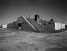
Building No. 370 was constructed in 1952 as an administrative office building for Sandia Corporation personnel. It was a long, one-story building with a flat roof and was constructed of concrete block on a concrete foundation. The building had multiple window and door openings. It had not been occupied since the site closed in 1962. Building No. 372 was constructed in 1956 of reinforced concrete and block. It measured approximately 36-feet by 16-feet. This building was used by the readiness crew, and for hazardous storage. Building No. 374 was the largest building constructed in the Base Spares Area. Built in 1956 of reinforced concrete, it measured approximately 129-feet by 49-feet. This building was also used for warehouse supply and equipment. It was razed sometime after February 1994. Building No. 367 was constructed in 1952 as field office building for the Atomic Energy Commission. This small structure measured 17 feet-4 inches in width by 25 feet-4 inches in length, and was a single story structure with a full basement below ground. It was constructed of monolithic reinforced concrete throughout. This small office has survived all of these years, and for good reason. The building was constructed in such a manner that it was virtually impossible for it to be destroyed by fire. The walls were constructed of 5-inch by 8-inch joists made entirely of concrete. Between each joist, which were set every 2 foot-1-inch on center, was a slab of concrete 2 ½ inches thick. The basement floor consists of a 4-inch thick solid concrete slab. The basement depth was 9-feet below ground. The total height of the basement was 11 ½ feet, with the basement height actually being 2 ½ feet above ground level. The basement had one window in it at ground level on the north side. The only access to the basement was from inside the structure itself. The basement consisted of a single utility room. A single set of concrete steps 6-feet in width and 8-feet in total length were used to gain access to the building. The steps were attached to the building on the west elevation. Steel pipe handrails were attached to each side of the steps. Upon entering the building through the outer door, a 6-foot by 6-foot outer vestibule was the first room within the structure. The vestibule was located on the south side of the building. To the immediate left was a doorway leading into the main office room. This room measured 16-feet in width by 18-feet in length. This room had eight windows, three windows on the east and west elevations, and two windows on the north elevation. Behind the vestibule room was another small room which measured 6 foot by 5 foot. This room was a storage room, and it also had a ladder/stairway to the basement. A third small room located behind the storage room also measured 6 foot by 5 foot. This room had a toilet and sink. All three small rooms were separated from the main office room and each other by 2” X 4” stud wall partitions. The walls were covered by sheets of asbestos cement board. The floors and ceiling as well as the roof were constructed of solid monolithic concrete. The floors were covered with asphalt tile. This small, yet almost indestructible office building was the AEC Records Office. All records pertaining to this particular site, and the material under the control of the Atomic Energy Commission, were stored here during the period of 1952-1962.
Building No. 365 (‘C’ Structure) was constructed in 1952. This building was probably the most critical structure built at this site in relation to the earliest nuclear weapons. The most critical operations involving fissionable material were performed in this building. The building was anything but a simple, rectangular structure approximately 105 feet in length and 29 feet wide. While it had a concrete foundation and brick walls, its looks were deceiving. It actually had two types of wall construction. Most of the building had 14-inch thick brick cavity walls. An air space (cavity) was built into the design of these walls, and metal ties joined the two cavity walls every 6th brick. There was no insulation in the walls of the structure. Some sections of the building had the same 14-inch thick brick cavity wall design, with the edition of an interior thick tile wall. The building had a flat roof, and the interior was divided into three sections. The southwestern elevation had a small concrete loading dock, with concrete steps up one side leading to two separate entrances. The loading dock had a concrete overhang. The first entrance had a door 3 foot-4 inches wide. This door led to a hallway that was 4 feet-10 ½ inches wide. This section of the building was the administrative section. Directly across from the personnel entrance door was the toilet and laundry rooms. The toilet room measured 9 feet-9 inches in width by 16 feet-6 inches in length. The toilet room had two showers, two sinks, two toilets, and a urinal. At the rear of the toilet room was a door leading into the laundry room. The laundry room measured 9 feet-9 inches in width by 5 feet in length. Lockers were installed in the laundry room. To the immediate right of the entrance door about 5 ½ feet down the hallway was a door leading to an office area. This office area measured 10 feet in width by 26 feet-6 inches in length. The office had an asphalt tile floor. Adjacent to the entry door to the office area, was another door that opened into a storage room area. This room measured 12 feet in width by 26 feet-6 inches in length. The second entrance on the loading dock was a double-door entrance, and was 6 feet-4 inches in width. This entrance led into the same hallway as the first entrance. The entrance opened into the hallway about midway down the hall. A solid concrete block wall on the other side of this entrance door was 24 feet-6 inches in length.
On the other side of this wall was the second section of the building, the equipment room. The equipment room measured 24 feet-6 inches in width by 21 feet-8 ½ inches in length. A loading dock on the backside of the building had steps and a double-door entrance that was 6 feet-4 inches in width. This outside entrance led directly into the equipment room. There were no doors to the equipment room from within the building. To the left of the second entrance door, the hallway adjacent to the equipment room led to a door into the third section of the building. This third section of the building was the most important. There were two rooms in this section. Surrounding the outside walls of these two rooms were the 14-inch thick brick and tile cavity walls. The tile was cemented to the interior brick wall. This provided an interior tile wall from ceiling to floor. The hallway in this area measured 5-feet in width. In the center of this hallway was a door into the first room. This room measured 25 feet-9 inches in width, by 21 feet-8 ½ inches in length. A door at the end of the hall opened into a second room. This room measured 20 feet in width by 26 feet-6 inches in length. This room also had a special exhaust air system installed in one of the exterior (tile covered) walls. This system was designed to reduce dust and airborne contamination. Both of these rooms were laboratory rooms, and each had tile walls and linoleum floors. The two laboratory rooms were very similar in design and the equipment installed was basically identical. Each room consisted of a series of cabinets and workbenches. They were of metal construction, and were installed against three of the four walls. The interior wall separating the two rooms was constructed of metal. On each side of this interior wall were identical cabinets with one large 16” by 20” by 8” stainless steel sink. The sinks were unique in the fact that they had knee operated control valves. This allowed a technician the freedom to hold an object with both hands while controlling the flow of water to the sink. Both rooms also had a monorail installed in the ceiling. This system was used to suspend weapons related components from the ceiling, and to move them from one side of the room to the other. Perhaps the most interesting part of these two rooms was the source pits, which were permanently constructed within the foundation of the building. Each room had a source pit located in the far left-hand corner of the room. The source pits were approximately 20 feet apart. They were constructed of stainless steel tubing. Each source pit was approximately 8 inches O.D., and 6-9/16 inches I.D. The source pit was 48 inches in depth from the floor line to the bottom of the pit. The pit itself was surrounded by concrete block below the floor line. Inside the source pit was a uniquely constructed device. This device was constructed of brass plate, brass tubing and stainless steel. The device was a basket that was constructed in such a way as to limit its ability to absorb neutrons. The device had two holding trays made entirely of solid brass plate. Each tray was 2-inches in height. A distance of 2-3/8 inches separated the two trays. The two trays, as well as a circular brass ring at the top, were connected together by 8-¾ inch steel rods. All connecting rods, tubing, and brass were bonded together by silver solder. Suspending the basket within the source pit was accomplished by 1/8” diameter aircraft cable. The cable was 43-½ inches in length, and was fastened to the basket by a threaded steel rod and hex nut. The basket fit very snug. The cable extended from the top of the basket through a cap which was inserted into the top of the pit to seal it. The cap was constructed of polyethylene. The top of the cap was made of stainless steel, and was fitted with a neoprene ‘O’ ring. The bottom of the cap was fitted with a solid lead shield and covered with a stainless steel bottom. The cap was approximately 6 inches thick. All welded joints for the cap had to be water tight and smooth. The pit was sealed so that air could not escape. The lead shield prevented radiation from escaping from the pit. The two source pits were used to store radioactive polonium neutron initiators. The two laboratory rooms within the ‘C’ Structure were used for the assembly and calibration of nuclear capsules. Personnel of the adjacent SAC base PMEL laboratory last occupied the building, after the site closed in 1962.
At the northernmost end of the Ordnance Storage Area a unique facility was constructed in 1957. This facility was specifically designed for this site only. It was a one-of-a-kind facility constructed for the exclusive use of the Atomic Energy Commission and Sandia Corporation. This facility was used to evaluate the environmental effects of cold weather on nuclear weapons. The facility known as the nuclear engineering test facility was constructed adjacent to one of the storage igloos along service road ‘C’. A concrete drive 12-feet in width and approximately 60-feet in length, led to the environmental test building. The test building itself was constructed of concrete and sheet metal. It measured 13 feet-4 inches in length by 8 feet in width. The foundation was a reinforced concrete slab. The floor was concrete. The walls and roof were constructed of sheet metal. Records indicate that the original cost of this structure in 1957 was $3,774.75. This small building was a utility building. It was constructed for the protection and climate control of the utility systems needed to operate the environmental test area. The building was electrically heated, and had a centrifugal roof exhauster capable of extracting 1200 CFM. The building was filled with electrical service equipment. Conduits extended from beneath the building to junction boxes along the perimeter of a concrete pad.
The concrete pad measured 35-feet in width by 50-feet in length and was constructed behind the environmental test building. A 7-foot high chain link fence was constructed at a distance of 5 feet from the edge of the concrete pad, and completely surrounded the entire pad and the test building. A 14-foot wide swing gate was used to gain access to the facility from service road ‘C’ along the concrete drive. The test building was situated to the right of the drive. The gate was situated at the end of the drive just before the test building. The concrete pad had to be illuminated at night for security purposes. There were four 150-watt floodlights on each 25-foot pole. There were four poles that were installed at each corner of the concrete pad. The lighting and 7-foot high chain link fence were needed to help protect the nuclear weapons which were parked on the concrete pad (hard-stand) for environmental testing. These weapons, which were no doubt covered from view, were still vulnerable sitting outside of their protective igloos for extended periods. Records indicate that the facility had been vacant and had been placed in a sterile condition status since December 13, 1972. The entire facility was completely demolished sometime during the years 1988-89. The test building, concrete pad, fencing, and utilities were all completely removed. This area has since been back-filled and there is absolutely no indication today that this facility ever existed at this site. Although construction had not been completed, the North River Depot was activated and partially occupied on November 1, 1951. This early activation was probably the result of the increased conflict in Korea. On December 15, 1951, the 3080th Aviation Depot Squadron was activated as a unit of the Air Material Command, and assumed control of the maximum storage area. 3080th personnel occupied the barracks, offices, and workstations, and the area became temporarily known as the 3080th Area. Construction of the weapons storage facility was completed on April 10, 1952. By the end of summer 1952, the 3080th was ready for full operations at North River Depot.[2]
Units Based There
- 3080th Aviation Depot Group
References
- ↑ Historic American Engineering Record. Loring Air Force Base, Weapons Storage Area, Northeastern corner of base at northern end of Maine Road, Limestone vicinity, Aroostook County, ME. On file with The Library of Congress.
- ↑ Official history of the 3080th Aviation Depot Group, U.S. Air Force Historical Research Agency.
External links
- History of Loring as well as the station
- Images of the base
- History of a Q Area
- Information on the buildings at the station

| Army |
|  | |||||||
|---|---|---|---|---|---|---|---|---|---|
| Air Force |
| ||||||||
| Navy |
| ||||||||
| Coast Guard |
| ||||||||
| National Guard |
| ||||||||