Capacitive power supply
A capacitive power supply, also called a capacitive dropper, is a type of power supply that uses the capacitive reactance of a capacitor to reduce the mains voltage to a lower voltage. There are two important limitations: First, the high withstanding voltage required of the capacitor, along with the high-capacitance required for a given output current, mean that this type of supply is generally used only in low-power applications. (Generally, a capacitor of a given size or budget can have a high voltage rating or high capacitance, but not both.) The second is that due to the absence of electrical isolation, the circuit must be encapsulated and isolated to avoid direct (galvanic) contact with the users.[1]
By the equation of state for capacitance, where , the current is limited to: 1 amp, per farad, per volt-rms, per radian (of phase). Or amps, per farad, per volt-rms, per hertz.


Structure
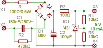
A capacitive power supply comprises a capacitor, C1, that with its reactance limits the current flowing through the rectifier bridge D1. To protect against voltage spikes during switching operations, there is a resistor, R1, connected in series with it. An electrolytic capacitor, C2, is used to smooth the DC voltage and the peak current (in the range of amps) in switching operations. Above right you can see a voltage regulator, which is formed by the current limiting resistor, R3, and the zener shunt regulator, IC1. If the voltage stability is not too important you can use a Zener diode as a regulator, which is a 2 terminal device and would eliminate R4 and R5 used for a resistive voltage divider in the schematic above.
Example

By changing the value of the example in the diagram by a capacitor with a value of 330 nF, we can provide a current of 20 mA. This way you can power up to 48 white LEDs (for example, 3.1 V/20 mA/20000 mcd) - that is provided connected in series. At 50 Hz, the 1.2 μF capacitor has a reactance of 2.653 kohm. By Ohm's law, the current is limited to 240 V/2653 Ω = 90 mA, assuming that voltage and frequency remain constant.
LEDs are connected in parallel with the 10 μF electrolytic filter capacitor. The four branches with 12 LEDs consume about 20 mA each. The diodes limit the voltage to about 40 V per branch. Since, normally, the circuit is connected directly to the network without galvanic isolation, we need a residual-current circuit breaker in any type of protection circuit used for this kind of LED light.
See also
References
External links
| Wikimedia Commons has media related to Capacitive power supply. |