Multivibrator 555
The 555 timer IC is a very versatile and useful component and can be used for many things, from giving clock pulses to switch debouncing and as an output transducer. The basic 555 IC is housed in an 8-pin carrier, and these come in DIL and SOIC formats. They run from 3-15V, and are generally quite hardy devices.
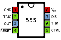
The 555 has 8 pins. The layout of these pins is shown to the right and the function of these pins in given in the table below.
| Pin | Abbrv. | Name | Function |
|---|---|---|---|
| 1 | GND | Ground Supply | This is the 0V Power Supply pin for the IC |
| 2 | TR | Trigger | A low voltage (less than 1/3 Vcc) starts the timer |
| 3 | Q | Output | This is where the output signal comes from |
| 4 | RST | Reset | A low state on this pin resets the timer, which will not be enabled until the Pin goes high again. |
| 5 | CV | Control Voltage | This is used to adject the trigger voltage. Usually, it is unused, and is connected to ground to avoid noise in the circuit. |
| 6 | THR | Threshold | This pin stops the timer when the voltage reaches 2/3 Vcc. |
| 7 | DIS | Discharge | This pin is connected to ground when the output goes low. This is used to control timing in certain applications. |
| 8 | +V | Positive Supply | The positive voltage supply to the chip. Must be between 3 and 15V. |
Basic Circuit
The basic 555 astable circuit is set up like this.
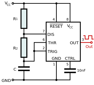
- At higher frequencies and loads, it is advisable to put a 100nF capacitor between Pin 5 and 0V.
The frequency and mark-space ratio are defined by the values of R1, R2 and C1 only. For a roughly even (1:1) mark-spce ratio, R1 is usually set at 1K, and the other resistor (R2) and capacitor are changed to alter the frequency. If better control over the mark-space ratio is required, use the next circuit.
Design equations
- .


There is an online calculator here that will give the frequency, high time and low time for a given set of components.
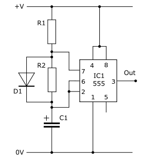
Variable mark-space ratio
This variation allow much easier control of the mark-space ratio without too much impact on the frequency. The only difference is a diode petween Pins 6 and 7, with the cathode at Pin 6. The effect of this is to shunt resistor R2 when charging C1. This means that C1 charges though R1 only. This removes R2 from the "high-time" equation, and make calculating the mark-space ratio easier and prevents the frequency from being altered excessively by changes in the mark-space ratio ( although this still happens to a certain extent).
Design equations
- .

- This is different to the design equation for the standard 555 Astable. (R2 instead of 2R2)


Mini-astable
This astable uses fewer components than the basic astable, and requires only the IC, one resistor and one capacitor, plus the Pin 5 capacitor for final versions.

This astable has a MSR of approximately 1:1, but this tends to increase under heavy current load, as the output does not swing fully to the power supply. This astable is not a reliable source of frequency, and should never be used where an accurate, stable clock is needed.
Design equations
- .


Pin 4 Enable
Pin 4 is normally held high, and in this state it does nothing. However, when Pin 4 is brought low, the 555 is disabled, and the output is held low. This can be used to turn an astable on when desired. An example of this is the double-astable bleeper, which uses the output from one astable to enable another, faster astable.
Pin 8 should not be used as the enable pin, as this will draw all the current needed to run the device from the triggering circuit.
Other astable circuits
Units of Design Equations
The units that the components values and frequency are measure in are the standard base units: ohms, farads and hertz. This are often inconvenient, as the value for componets are usually several orders of magnitude away from the base unit. It is possible to use more conveninet units to calculate the frequency, and the common combinations are given below:
| Resistance | Capacitance | Period | Frequency |
|---|---|---|---|
| Ω | F | s | Hz |
| MΩ | μF | s | Hz |
| kΩ | μF | ms | kHz |
This plugin consists of a single 555 Astable. This plugin is very versatile, and can be used for any number of things, but it often is used to give a clock to run a circuit. The plugin below gives a pulse of about 2 Hz with a very low mark-space ratio. The circuit diagram is given below.
This circuit obeys the following formulae with regards to its frequency and mark space ratio.
- .
- This is different to the design equation for the standard 555 Astable. (R2 instead of 2R2)


The values below give a frequency of about 2 Hz, with a mark-space ratio of about 1:50.
The stripboard layout is as shown below with a component list.
 |
|
Variations
Enable pin
To give this plugin an enable pin, replace the wire link from Pin 4 to +V with a 10K resistor going from Pin 4 to ground (Pin 1). Then add a header pin to Pin 4. A high signal on this pin will cause the astable to function, a low will disable it, locking the output low.