This circuit is useful for applications where a signal has to pulse fast, and slow down to a stop, such as electronic dice, games timers, etc. It gives an output like the one below:

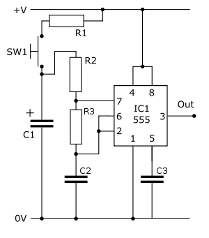
The way the diminishing frequency is achieved is by using another capacitor to run the timing components. First, the switch SW1 is closed, so that capacitor C1 is charged through R1. When the switch is released, C1 begins to discharge through the timing circuit. As the exponentially decreasing voltage from this capacitor falls, it slows the rate of charging of the timing capacitor, which decreases the output frequency. Eventually, the voltage from the control capacitor falls below 2/3 supply voltage, and the astable stops. The circuit diagram is given below.
 |
|
These values give a frequency of about 100 Hz, which runs down in about 30 seconds. Experiment with values to get the effect you want, bearing in mind the following guidelines:
The size of the control capacitor, C1, governs the time it takes to run down. Bear in mind that for a very large value of C1, R1 must be small enough to allow the control capacitor to charge in the time that SW1 is pressed down.
R2 and R3 must have high values, as if they are too small, the control capacitor, C1, will be discharged too quickly, and the astable will "run down" in a very short time. This also means that the addition of the 100R resistor for charging the capacitor safely does not significantly alter the timing of the circuit while the switch is pressed down.