Video Graphics Array
Video Graphics Array (VGA) is a graphics standard for video display controller first introduced with the IBM PS/2 line of computers in 1987,[1][2][3] following CGA and EGA introduced in earlier IBM personal computers. Through widespread adoption, the term has also come to mean either an analog computer display standard, the 15-pin D-subminiature VGA connector, or the 640×480 resolution characteristic of the VGA hardware.
 | |
| Release date | 1986 |
|---|---|
| Cards | |
| Entry-level |
|
| Mid-range |
|
| High-end |
|
| History | |
| Predecessor | Enhanced Graphics Adapter |
| Successor |
|
VGA was the last IBM graphics standard to which the majority of PC clone manufacturers conformed, making it the lowest common denominator that virtually all post-1990 PC graphics hardware can be expected to implement.[4] It was officially followed by IBM's Extended Graphics Array (XGA) standard but instead was effectively superseded by numerous slightly different extensions to VGA made by clone manufacturers, collectively known as Super VGA.
Today, the VGA analog interface is used for high-definition video, including resolutions of 1080p and higher. While the transmission bandwidth of VGA is high enough to support even higher resolution playback, there can be picture quality degradation depending on cable quality and length. How discernible this degradation depends on the individual's eyesight and the display, though it is more noticeable when switching to and from digital inputs like HDMI, DVI or DisplayPort.
Output capabilities
The VGA supports both All Points Addressable graphics modes and alphanumeric text modes.
Standard graphics modes
Standard graphics modes are:
- 640×480 in 16 colors or monochrome[5] (the latter matching IBM's lesser Multi-Color Graphics Array standard)
- 640×350 or 640×200 in 16 colors or monochrome (EGA compatibility mode)
- 320×200 in 4 or 16 colors
- 320×200 in 256 colors (Mode 13h)
The 640×480 16-color and 320×200 256-color modes had fully redefinable palettes, with each entry selectable from within an 18-bit (262,144-color) RGB table, although the high resolution mode is most commonly familiar from its use with a fixed palette under Microsoft Windows. The other color modes defaulted to standard EGA or CGA compatible palettes (including the ability for programs to redefine the 16-color EGA palette from a master 64-color table), but could still be redefined if desired using VGA-specific programming.
Higher-resolution and other display modes
Higher-resolution and other display modes are also achievable, even with standard cards and most standard monitors – on the whole, a typical VGA system can produce displays with any combination of:
- 512 to 800 pixels wide, in 16 colors (including 640, 704, 720, 736, 768...), or
- 256 to 400 pixels wide, in 256 colors (including 320, 360, 384...)
with heights of:
- 200, or 350 to 410 lines (including 400-line) at 70 Hz refresh rate, or
- 224 to 256, or 448 to 512 lines (including 240 or 480-line) at 60 Hz refresh rate
- 512 to 600 lines at reduced vertical refresh rates (down to 50 Hz, and including e.g. 528, 544, 552, 560, 576-line), depending on individual monitor compatibility.
(175 to 205 line modes may be possible at 70 Hz, and 256 to 300 lines in the 50 to 60 Hz refresh rate range, as well as horizontal widths below 256/512, but these are of little practical use)
For example, high resolution modes with square pixels are available at 768×576 or 704×528 in 16 colors, or medium-low resolution at 320×240 with 256 colors; alternatively, extended resolution is available with "fat" pixels and 256 colors using, e.g. 400×600 (50 Hz) or 360×480 (60 Hz), and "thin" pixels, 16 colors and the 70 Hz refresh rate with e.g. 736×410 mode.
"Narrow" modes such as 256×224 tend to preserve the same pixel ratio as in e.g. 320×240 mode unless the monitor is adjusted to stretch the image out to fill the screen, as they are derived simply by masking down the wider mode instead of altering pixel or line timings, but can be useful for reducing memory requirements and pixel addressing calculations for arcade game conversions or console emulators.
Standard text modes
Standard text modes:
- 80×25 character display, rendered with a 9×16 pixel font, with an effective resolution of 720×400 in either 16 colors or monochrome, the latter being compatible with legacy MDA-based applications.[6]
- 40×25, using the same font grid, for an effective resolution of 360×400
- 80×43 or 80×50 (8×8 font grid) in 16-colors, with an effective resolution of 640×344 (EGA-compatible) or 640×400 pixels.
As with the pixel-based graphics modes, additional text modes are technically possible (as VGA resolution settings are notionally calculated from character-grid dimensions) with an overall maximum of about 100×80 cells and an active area spanning about 88×64 cells, but these are rarely used as it usually makes much more sense to just use a graphics mode – with a small, perhaps proportional font – if a larger text display is required. One variant that is sometimes seen is 80×30 or 80×60, using an 8×16 or 8×8 font and an effective 640×480 pixel display, which trades use of the more flickery 60 Hz mode for an additional 5 or 10 lines of text and square character blocks (or, at 80×30, square half-blocks).
Technical details
Circuitry design
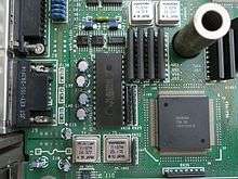
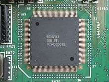
VGA is referred to as an "Array" instead of an "adapter" because it was implemented from the start as a single chip – an application-specific integrated circuit (ASIC) which replaced both the Motorola 6845 video address generator and the dozens of discrete logic chips that covered the full-length ISA boards of the MDA and CGA. More directly, it replaced the five custom LSIs (including a custom replacement for the 6845) and many discrete logic chips on the EGA board. Its single-chip implementation allowed the VGA to be placed directly on a PC′s motherboard with a minimum of difficulty, which in turn increased the reliability of the video subsystem by reducing the number of component connections, since the VGA required only video memory, timing crystals and an external RAMDAC.[7] As a result, the first IBM PS/2 models were equipped with VGA on the motherboard, in contrast to all of the "family one" IBM PC desktop models – the PC, PC/XT, and PC AT – which required a display adapter installed in a slot in order to connect a monitor.
Specifications
The original VGA specifications are as follows (supporting e.g. no hardware sprites):
- 256 KB Video RAM (The very first cards could be ordered with 64 KB or 128 KB of RAM, at the cost of losing some or all high-resolution 16-color modes.)
- 16-color and 256-color paletted display modes.
- 262,144-color global palette (6 bits, and therefore 64 possible levels, for each of the red, green, and blue channels via the RAMDAC)
- Selectable 25.175 MHz[8] or 28.322 MHz master pixel clock
- Usual line rate fixed at 31.46875 kHz
- Maximum of 640 horizontal pixels[9]
- Maximum of 480 lines[9]
- Refresh rates at up to 70 Hz[10]
- Vertical blank interrupt (Not all clone cards support this.)
- Planar mode: up to 16 colors (4 bit planes)
- Packed-pixel mode: 256 colors (Mode 13h)
- Hardware smooth scrolling support
- No Blitter, but supports very fast data transfers via "VGA latch" registers
- Some "Raster Ops" support
- Barrel shifter
- Split screen support
- 0.7 V peak-to-peak[11]
- 75 ohm double-terminated impedance (18.7 mA, 13 mW)
As well as the standard modes, VGA can be configured to emulate many of the modes of its predecessors (EGA, CGA, and MDA), including their reduced global color palettes (with particular pre-set colors chosen from the VGA palette for text and 4- or 16-color, 200-line modes) and coarser text font grids. Compatibility is almost full at BIOS level, but even at register level, a very high value of compatibility is reached. VGA is not directly compatible with the special IBM PCjr or HGC video modes, despite having sufficient resolution, color, refresh rate and memory capabilities; any emulation of these modes has to be performed in software instead.
Signal timings
The intended standard value for the horizontal frequency of VGA is exactly double the value used in the NTSC-M video system, as this made it much easier to offer optional TV-out solutions or external VGA-to-TV converter boxes at the time of VGA's development, a technique proposed by Zia Shlaimoun; it is also at least nominally twice that of CGA, which itself used broadcast-frequency monitors, essentially tunerless televisions with more direct signal inputs. The formula for the VGA horizontal frequency is thus (60 ÷ 1001) × 525 kHz = 4500 ÷ 143 kHz ≈ 31.4685 kHz, obtained in practice by the method common to all raster-based computer graphics of using a particular crystal oscillator or PLL frequency for the pixel clock and deriving all other horizontal and vertical frequencies by integer division. In this case, a 25.175 MHz or 28.322 MHz pixel clock, counting 800 or 900 pixels per line, arriving at 31.46875 or 31.46889 kHz (and from there, 525 or 449 lines to arrive at 59.94 Hz or 70.09 Hz); the tiny mismatch (7 to 12ppm) is easily accounted for by, and is well within the limits of the retrace synchronisation system. In fact, CGA itself was further adrift (as it could only scan 262 lines per progressive frame, instead of 262.5 to match NTSC's interlaced nature), and the limited precision of quartz oscillators - and their tendency to drift slightly with temperature and supply voltage - means real cards will have slightly higher or lower frequencies whose variance vs the nominal figures can easily exceed the inherent mismatch.
All derived VGA timings (i.e. those which still use the master 25.175 and 28.322 MHz crystals and, to a lesser extent, the nominal 31.469 kHz line rate) can be varied widely by software that bypasses the VGA firmware interface and communicates directly with the VGA hardware, as many MS-DOS based games did. However, only the standard modes, or modes that at least use almost exactly the same H-sync and V-sync timings as one of the standard modes, can be expected to work with the original late-1980s and early-1990s VGA monitors. The use of other timings may in fact damage such monitors and thus was usually avoided by software publishers. Third-party "multisync" CRT monitors were usually much more flexible, and in combination with "super EGA", VGA, and later SVGA graphics cards using extended modes, could display a much wider range of resolutions and refresh rates at wholly arbitrary sync frequencies and pixel clock rates (within a particular lower/upper range, depending on model, typically encompassing a range spanning CGA's 15.7 kHz to SVGA and XGA's 36 kHz at a minimum, and including the 18.4, 21.8, 24.8 and 31.5 kHz of MDA/Hercules, EGA, "25kHz medium resolution" (a standard popularised by several Japanese domestic-market computers) and VGA along the way), commonly reaching 640x400 thru 720x480 (at 56 thru 72 Hz), 752x410, 800x560 and 800x600 as standard or near-standard settings.
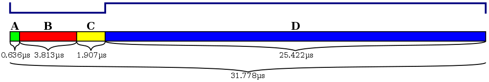
For the most common VGA mode (640×480 "60 Hz" non-interlaced), the horizontal timings are:[12][13]
| Parameter | Value | Unit |
|---|---|---|
| Pixel clock frequency | 25.175 | MHz[14] |
| Horizontal frequency | 31.469 | kHz |
| Horizontal pixels | 640 | |
| Horizontal sync polarity | Negative | |
| Total time for each line | 31.778 | µs |
| Front porch (A) | 0.636 | µs |
| Sync pulse length (B) | 3.813 | µs |
| Back porch (C) | 1.907 | µs |
| Active video (D) | 25.422 | µs |
(Total horizontal sync and blanking time = 6.356 µs; equivalent to pixel widths of A = 16, B = 96, C = 48, D = 640 and each complete line = 800)
NB. The same general layout applies, merely at a lower frequency, for the vertical timings.
These timings are the same in the higher frequency mode, but all pixel counts are correspondingly multiplied by 9/8ths – thus, 720 active pixels, 900 total per line, and a 54 pixel back porch.
The vertical timings are:
| Parameter | Value | Unit |
|---|---|---|
| Vertical lines | 480 | |
| Vertical sync polarity | Negative | |
| Vertical frequency | 59.94 | Hz |
| Total time for each frame | 16.683 | ms |
| Front porch (A) | 0.318 | ms |
| Sync pulse length (B) | 0.064 | ms |
| Back porch (C) | 1.048 | ms |
| Active video (D) | 15.253 | ms |
(Total vertical sync and blanking time 1.43 ms; equivalent to line periods of A = 10, B = 2, C = 33, D = 480 and each complete frame = 525)
These timings are somewhat altered in "70Hz" mode, as although it uses the same line rate, its frame rate is not quite exactly 7/6ths that of "60 Hz", despite 525 dividing cleanly into 7 – and, of course, 480/400 is itself a larger 6:5 ratio. Instead, it compromises on a 449-line frame (instead of the expected 450), with the back porch extended to 34 lines, and the front porch to 13, with an unaltered 2-line sync pulse – and the active image taking up 89% of the total scan period rather than 91%. The monitor is triggered into synchronising at the higher frame scan rate (and, with digital displays such as LCDs, the higher horizontal pixel density) by use of a positive-polarity VSync pulse, versus the negative pulse of 60 Hz mode.
Depending on manufacturer, the exact details of active period and front/back porch widths, particularly in the horizontal domain, may vary slightly. This does not usually cause a problem as the porches are merely intended to act as blanked-video buffers offering a little overscan space between the active area and the sync pulse (which triggers, in traditional CRT monitors, the phosphor beam deflection "flyback" to the upper or left hand side of the tube) and thus can be safely overrun into by a certain amount when everything else is operating correctly. The relationship between the front and back porches can also be altered within certain limits, which makes possible special features such as software-based image alignment with certain graphics cards (centering the image within the monitor frame by adjusting the location of the active screen area between the horizontal and vertical porches, rather than relying wholly upon the adjustment range offered by the monitor's own controls which can sometimes be less than satisfactory).
This buffer zone is typically what is exploited to achieve higher active resolutions in the various custom screen modes, by deliberately reducing porch widths and using the freed-up scan time for active pixels instead. This technique can achieve an absolute maximum of 704 pixels horizontally in 25 MHz mode and 792 at 28 MHz without altering the actual sync width (in real-world cases, e.g. with 800 pixel wide mode, the sync pulse would be shortened and a small porch area left in place to prevent obvious visual artefacting), and as much as 523 or 447 lines at the standard 60 and 70 Hz refresh rates (again, it is usually necessary to leave SOME porch lines intact, hence the usual maximum of 410 or 512 lines at these rates, and the 50 Hz maximum being 600 lines rather than 626). Conveniently, the practical limits of these techniques are not quite high enough to overflow the available memory capacity of typical 256 KB cards (800×600 consuming 235 KB, and even the theoretical 832×624 requiring "only" 254 KB), so the only concerns remain those of monitor compatibility.
Typical uses of selected modes
640×400 @ 70 Hz is traditionally the video mode used for booting those VGA-compatible x86 personal computers[15] that show a graphical boot screen (text-mode boot uses 720×400 @ 70 Hz). This convention has been eroded in recent years, however, with POST and BIOS screens moving to higher, and often automatically adapted resolutions dependent on the connected monitor (800x600 as a minimum, but 1024x768, 1280x800, 1440x900 and 1920x1080 are not unknown), taking advantage of EDID data and vector or other resizable graphics, along with use of PS/2 or USB mouse detection instead of relying on keyboard alone, to provide a visual experience much closer to that of a fully booted operating system. Should the detection fail, however, or the user cancel the high-quality graphics (either temporarily with a keyboard shortcut, or permanently via a BIOS setting), the old standard mode is generally reasserted.
640×480 @ 60 Hz is the default Windows graphics mode (usually with 16 colors),[15] up to Windows 2000. It remains an option in XP and later versions via the boot menu "low resolution video" option and per-application compatibility mode settings, despite Windows now defaulting to 1024x768 (and then only when running the default universal video driver and/or unable to detect the connected display's native resolution) and generally not allowing any resolution below 800x600 to be set. The need for such a low-quality, universally compatible fallback has diminished since the turn of the millennium, as VGA-signalling-standard screens or adaptors unable to show anything beyond the original resolutions have become increasingly rare, and are now most likely to be employed for specialist uses by enthusiasts - for example, arcade cabinet gaming PC conversions, or driving pico-projectors from wearable computers - instead of blithely connected up as a main desktop display by an unsuspecting casual user; however, as it retains such niche utility, the ability to deliberately set it (and indexed 16 or 256 colour modes besides, instead of now-normal 16/24/32-bit direct colour), nowadays as a special rather than default mode, has been preserved.
320×200 @ 70 Hz is the most common mode for VGA-era PC games, using exactly the same timings as the 640×400 mode, but halving the pixel rate (and, in 256-color mode, doubling the bit-depth of each pixel) and displaying each line of pixels twice.
The actual timings vary slightly from the defined standard. For example, for 640×480 @ 60 Hz, a 25.17 µs active video time with a pixel frequency of 25.175 MHz gives 634 pixels, rather than the expected 640. Given the similarity of the frequency and line length, this may be due to typographical errors that were never detected or corrected; at the standard clock (equal to 39.722ns per pixel), the correct nominal active period should instead be 25.422µs. Otherwise, if the spec were true, that would imply a faster 39.328ns / 25.427 MHz dot clock. Further examination of the other timing details (e.g. checking if the line period/frequency and refresh rate are still correct, the total pixel or line count when active plus front/back porch and sync pulse times are added together) may better reveal where and how the discrepancy was introduced, as the master clock and fundamental dividers are well known and provide an easy reference to compare any other claim against.
Connectors
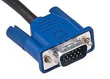
VGA uses a DE-HD15 connector (often erroneously called "DB-15", in confusion with the larger, lower density Joystick/MIDI connector found on most PC soundcards and some ATX panels). This connector fits on the mounting tab of an ISA expansion card.

An alternative method of connecting VGA devices that maintains very high signal quality even over extended cable runs is the BNC connector, typically used as a group of five connectors, one each for Red, Green, Blue, Horizontal Sync, and Vertical Sync. With BNC, the coaxial wires are fully shielded end-to-end and through the interconnect so that no crosstalk or external interference is possible, easily doubling standard VGA's maximum reliable distance of 15 metres, and reaching 40–50 metres with the aid of nothing more than a simple signal booster.
However, BNC connectors are relatively large compared to the 15-pin D-shell, and some attention is needed - vs the insertion of that single plug - to ensure each cable goes to the correct socket; although the core RGB lines are coloured appropriately, the sync wires can be various arbitrary colours (yellow, grey, white, black) and although standards do exist for these it is often unclear which is the correct arrangement at the point of connection and it can become a process of elimination. Additionally, extra lines such as +5V DC and DDC / DDC2 signals are not supported using BNC connectors.
Beyond around 50 metres, or 30 metres without any active amplification, cable capacitance can become a problem for the analogue signals, noticeably reducing horizontal image resolution and causing poor sync. In these cases, other methods such as using "SPI" digital codecs connected by shielded CAT5 network-grade cable, or even framegrabbing plus TCP/IP networking are employed to transmit the image long-distance, even though it may still travel the first and last few tens of centimetres as analogue VGA, or any of a variety of other standards that the codecs may support.
Standard text modes
The BIOS offers some text modes for a VGA adapter, which have 80×25, 40×25, 80×43 or 80×50 text grid. Each cell may choose from one of 16 available colors for its foreground and eight colors for the background; the eight background colors allowed are the ones without the high-intensity bit set. Each character may also be made to blink; all that are set to blink will blink in unison. The blinking option for the entire screen can be exchanged for the ability to use all 16 colors for background. All of these options are the same as those on the CGA adapter as introduced by IBM.
Like EGA, VGA supports having up to 512 different simultaneous characters on screen, albeit in only 8 foreground colors, by rededicating one color bit as the highest bit of the character number. The glyphs on 80×25 mode are normally made of 9×16 pixels. Users may define their own character set by loading a custom font onto the card. As character data is only eight bits wide on VGA, just as on all of its predecessors, there is usually a blank pixel column between any two horizontally adjacent glyphs. However, some characters are normally made nine bits wide by repeating their last column instead of inserting a blank column, especially those defining horizontally connected IBM box-drawing characters. This functionality is hard-wired to the character numbers C0hex to DFhex, where all horizontally connecting characters are found in code page 437 and its most common derivatives. The same column-repeating trick was already used on the older MDA hardware with its 9×14 pixel glyphs, but on VGA it can be turned off when loading a font in which those character numbers do not represent box drawing characters.[16][17]
Monochrome modes
VGA adapters usually support both monochrome and color modes, though the monochrome mode is almost never used, and support for the full set of MDA text mode attributes (intense, underline) is often missing. Black and white text on nearly all modern VGA adapters is drawn by using gray colored text on a black background in color mode. VGA monochrome monitors intended primarily for text were sold, but most of them will work at least adequately with a VGA adapter in color mode. Occasionally, a faulty connection between a modern monitor and video card will cause the VGA part of the card to detect the monitor as monochrome; this will cause the BIOS and initial boot sequence to appear in greyscale. Usually, once the video card's drivers are loaded (for example, by continuing to boot into the operating system), they will override this detection and the monitor will return to color.
Addressing details

The video memory of the VGA is mapped to the PC's memory via a window in the range between segments 0xA0000 and 0xBFFFF in the PC's real mode address space (A000:0000 and B000:FFFF in segment:offset notation). Typically, these starting segments are:
- 0xA0000 for EGA/VGA graphics modes (64 KB)
- 0xB0000 for monochrome text mode (32 KB)
- 0xB8000 for color text mode and CGA-compatible graphics modes (32 KB)
Due to the use of different address mappings for different modes, it is possible to have a monochrome adapter (i.e. MDA or Hercules) and a color adapter such as the VGA, EGA, or CGA installed in the same machine. At the beginning of the 1980s, this was typically used to display Lotus 1-2-3 spreadsheets in high-resolution text on a monochrome display and associated graphics on a low-resolution CGA display simultaneously. Many programmers also used such a setup with the monochrome card displaying debugging information while a program ran in graphics mode on the other card. Several debuggers, like Borland's Turbo Debugger, D86 and Microsoft's CodeView could work in a dual monitor setup. Either Turbo Debugger or CodeView could be used to debug Windows. There were also DOS device drivers such as ox.sys, which implemented a serial interface simulation on the monochrome display and, for example, allowed the user to receive crash messages from debugging versions of Windows without using an actual serial terminal. It is also possible to use the "MODE MONO" command at the DOS prompt to redirect the output to the monochrome display. When a monochrome adapter was not present, it was possible to use the 0xB000–0xB7FF address space as additional memory for other programs (for example by adding the line "DEVICE=EMM386.EXE I=B000-B7FF" into config.sys, this memory would be made available to programs that can be "loaded high", that is loaded into high memory.)
Color palette
The VGA color system is backward compatible with the EGA and CGA adapters, and adds another level of indirection to support 256 8-bit-colors.
CGA was able to display 16 fixed colors, and EGA extended this by using 16 palette registers, each containing a color value from a 64-color palette. The default EGA palette values were chosen to look like the CGA colors, but it's possible to remap each color. (Note: This works in graphics and text modes.) The signals from the EGA palette entries will drive a set of six signal lines on the EGA output, with two lines corresponding to one color (off, dark, normal and bright, for red, green and blue).
VGA further extends this scheme by adding 256 color registers, 3×6 bit each for a total of 262,144 colors to choose from. These color registers are by default set to match the 64 default EGA colors. The values from these registers drive a DAC, which in turn drives three signal lines, one for red, green and blue. (Because analog signals are used, a default VGA cable can carry a theoretically unlimited number of color values.)
Like EGA uses the CGA color value to address a palette entry, the VGA hardware will also use the palette entries not directly as signal levels but as indexes to the color registers. Therefore, in the 16-color modes, the color value from the RAM will reference a palette register and that palette register will select a color register. E.g. the default palette entry for brown (on CGA: 4 (red) + 2 (green)), contains 0x14 (dark green + normal red) on the EGA palette. The corresponding VGA color register 0x14 is preset to (42,21,0, or #aa5500).
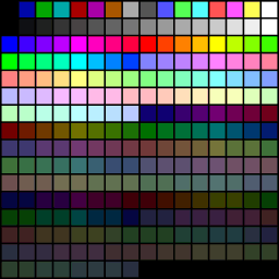
In the 256-color modes, the palette registers are ignored and the DAC is set to combine four 2-bit color values, one from each plane, into the original 8-bit-value. The CPU interface combined the 4 planes in exactly the same way (a feature called "chain-4") so that the pixel appeared to the CPU as a packed 8-bit value. This color number is exactly which color register is used. Since the colors 0 ... 15 are still supposed to result in the CGA colors, the color registers are not preset to contain the EGA palette; instead it contains the 16 CGA colors in the first entries. The other entries are 16 gray levels from black to white and 9 groups of 24 color values. The remaining 8 entries are black (see picture).[18]
| CGA | EGA | VGA | RGB | Web | Example |
|---|---|---|---|---|---|
| 0x0 | 0x0 | 0,0,0 | 0,0,0 | #000000 | black |
| 0x1 | 0x1 | 0,0,42 | 0,0,170 | #0000AA | blue |
| 0x2 | 0x2 | 0,42,0 | 0,170,0 | #00AA00 | green |
| 0x3 | 0x3 | 0,42,42 | 0,170,170 | #00AAAA | cyan |
| 0x4 | 0x4 | 42,0,0 | 170,0,0 | #AA0000 | red |
| 0x5 | 0x5 | 42,0,42 | 170,0,170 | #AA00AA | magenta |
| 0x6 | 0x14 | 42,21,0 | 170,85,0 | #AA5500 | brown |
| 0x7 | 0x7 | 42,42,42 | 170,170,170 | #AAAAAA | gray |
| 0x8 | 0x38 | 21,21,21 | 85,85,85 | #555555 | dark gray |
| 0x9 | 0x39 | 21,21,63 | 85,85,255 | #5555FF | bright blue |
| 0xA | 0x3A | 21,63,21 | 85,255,85 | #55FF55 | bright green |
| 0xB | 0x3B | 21,63,63 | 85,255,255 | #55FFFF | bright cyan |
| 0xC | 0x3C | 63,21,21 | 255,85,85 | #FF5555 | bright red |
| 0xD | 0X3D | 63,21,63 | 255,85,255 | #FF55FF | bright magenta |
| 0xE | 0x3E | 63,63,21 | 255,255,85 | #FFFF55 | yellow |
| 0xF | 0x3F | 63,63,63 | 255,255,255 | #FFFFFF | white |
| 0x00 | 0x01 | 0x02 | 0x03 | 0x04 | 0x05 | 0x06 | 0x07 | 0x08 | 0x09 | 0x0A | 0x0B | 0x0C | 0x0D | 0x0E | 0x0F |
| 0x10 | 0x11 | 0x12 | 0x13 | 0x14 | 0x15 | 0x16 | 0x17 | 0x18 | 0x19 | 0x1A | 0x1B | 0x1C | 0x1D | 0x1E | 0x1F |
| 0x20 | 0x21 | 0x22 | 0x23 | 0x24 | 0x25 | 0x26 | 0x27 | 0x28 | 0x29 | 0x2A | 0x2B | 0x2C | 0x2D | 0x2E | 0x2F |
| 0x30 | 0x31 | 0x32 | 0x33 | 0x34 | 0x35 | 0x36 | 0x37 | 0x38 | 0x39 | 0x3A | 0x3B | 0x3C | 0x3D | 0x3E | 0x3F |
Programming
"Unchaining" the 256 KB VGA memory into four separate "planes" makes VGA's 256 KB of RAM available in 256-color modes. There is a trade-off for extra complexity and performance loss in some types of graphics operations, but this is mitigated by other operations becoming faster in certain situations:
- Single-color polygon filling could be accelerated due to the ability to set four pixels with a single write to the hardware.
- The video adapter could assist in copying video RAM regions, which was sometimes faster than doing this with the relatively slow CPU-to-VGA interface.
- The use of multiple video pages in hardware allowed double buffering, triple buffering or split screens, which, while available in VGA's 320×200 16-color mode, was not possible using stock Mode 13h.
- Most particularly, several higher, arbitrary-resolution display modes were possible, all the way up to the programmable limit of 800×600 with 16 colors (or 400×600 with 256 colors), as well as other custom modes using unusual combinations of horizontal and vertical pixel counts in either color mode.
Software such as Fractint, Xlib and ColoRIX also supported tweaked 256-color modes on standard adaptors using freely-combinable widths of 256, 320, and 360 pixels and heights of 200, 240 and 256 (or 400, 480 and 512) lines, extending still further to 384 or 400 pixel columns and 576 or 600 (or 288, 300). However, 320×240 was the best known and most frequently used, as it offered a standard 40-column resolution and 4:3 aspect ratio with square pixels. "320×240×8" resolution was commonly called Mode X, the name used by Michael Abrash when he presented the resolution in Dr. Dobb's Journal.
The highest resolution modes were only used in special, opt-in cases rather than as standard, especially where high line counts were involved. Standard VGA monitors had a fixed line scan (H-scan) rate – "multisync" monitors being, at the time, expensive exotica – and so the vertical/frame (V-scan) refresh rate had to be reduced in order to accommodate them, which increased visible flicker and thus eye strain. For example, the highest 800×600 mode, being otherwise based off the matching SVGA resolution (with 628 total lines), reduced the refresh rate from 60 Hz to about 50 Hz (and 832×624, the theoretical maximum resolution achievable with 256kb at 16 colors, would have reduced it to about 48 Hz, barely higher than the rate at which XGA monitors employed a double-frequency interlacing technique to mitigate full-frame flicker).
These modes were also outright incompatible with some monitors, producing display problems such as picture detail disappearing into overscan (especially in the horizontal dimension), vertical roll, poor horizontal sync or even a complete lack of picture depending on the exact mode attempted. Due to these potential issues, most VGA tweaks used in commercial products were limited to more standards-compliant, "monitor-safe" combinations, such as 320×240 (square pixels, three video pages, 60 Hz), 320×400 (double resolution, two video pages, 70 Hz), and 360×480 (highest resolution compatible with both standard VGA monitors and cards, one video page, 60 Hz) in 256 colors, or double the H-rez in 16-color mode.
Hardware manufacturers
Several companies produced VGA compatible graphic board models.[19]
- ATI: Graphics Solution Plus, Wonder series, Mach series
- S3 Graphics: S3 911, 911A, 924, 801, 805, 805i, 928, 805p, 928p, S3 Vision series, S3 Trio series
- Matrox: MAGIC RGB
- Plantronics: Colorplus
- Paradise Systems (defunct): PEGA 1, PEGA 1a, PEGA 2a
- Tseng Labs: ET3000, ET4000, ET6000
- Cirrus Logic: CL-GD400, CL-GD500 and CL-GD5000 series
- Trident Microsystems: TVGA 8000 series, TVGA 9000 series, TGUI9000 series
- IIT
- NEC
- Chips and Technologies
- SiS
- Tamerack
- Realtek
- Oak Technology
- LSI
- Hualon
- Cornerstone Imaging
- Winbond
- AMD
- Western Digital
- Intergraph
- Texas Instruments
- Gemini (defunct)
- Genoa (defunct)
Successors
Super VGA (SVGA)
Super VGA (SVGA) is a display standard developed in 1988, when NEC Home Electronics announced its creation of the Video Electronics Standards Association (VESA). The development of SVGA was led by NEC, along with other VESA members including ATI Technologies and Western Digital. SVGA enabled graphics display resolutions up to 800×600 pixels, 36% more than VGA's maximum resolution of 640×480 pixels.[20]
Extended Graphics Array (XGA)
Extended Graphics Array (XGA) is an IBM display standard introduced in 1990. Later it became the most common appellation of the 1024 × 768 pixels display resolution.
See also
- Graphic display resolutions
- List of color palettes
- List of video connectors
- List of monochrome and RGB palettes
- List of 16-bit computer hardware palettes
- List of defunct graphics chips and card companies
- Super VGA
- AX-VGA (for Japanese AX architecture computers)
- DOS/V
References
- Petzold, Charles (July 1987). "Triple standard: three new video modes from IBM". PC Magazine. Ziff Davis. Retrieved 2020-04-13.
- Polsson, Ken. "Chronology of IBM Personal Computers". Archived from the original on 2015-02-21. Retrieved 2015-01-28.
- "What is VGA (Video Graphics Array)?". Retrieved 2018-08-13.
- Dr. Jon Peddie. "Famous Graphics Chips: IBM's VGA. The VGA was the most popular graphics chip ever". Retrieved 2020-04-13.
It is said about airplanes that the DC3 and 737 are the most popular planes ever built, and the 737, in particular, the best-selling airplane ever. The same could be said for the ubiquitous VGA, and its big brother the XGA. The VGA, which can still be found buried in today’s modern GPUs and CPUs, set the foundation for a video standard, and an application programming standard.
- Hinner, Martin. "VGA Timings". Archived from the original on 27 October 2012. Retrieved 7 November 2012.
- Abrash, Michael. "How 360×480 in 256 color mode works". Graphics Programming Black Book. Archived from the original on 23 April 2012. Retrieved 7 November 2012.
- Thompson, Stephen (1988). "VGA ‒ Design choices for a new video subsystem". IBM Systems Journal. IBM. 27 (2): 185‒197. doi:10.1147/sj.272.0185.
- "VGA Signal 640 x 480 @ 60 Hz Industry standard timing".
- PS/2 Video Subsystem Technical Reference Manual 1992
- "VGA Signal timings". Archived from the original on 2016-06-20.
- "VGA Electrical FAQ". Archived from the original on 2016-04-29.
- "Javier Valcarce VGA timings page". Archived from the original on 2015-01-02.
- HP D1194A Super VGA Display & HP D1195A Erognomic Super VGA Display Installation Guide, Hewlett Packard
- Article "Re: VGA specifications ,where ?" posted 19 November 1997 to sci.electronics.design newsgroup by Jeroen Stessen
- "ePanorama.net - Circuits". Archived from the original on 2009-02-27. 090425 epanorama.net
- J. D. Neal (1998). "Hardware Level VGA and SVGA Video Programming Information". FreeVGA Project. Archived from the original on 2010-09-01. Retrieved 2010-11-18.
- Maresin, Innocenti. "VGA console basics and Linux console-tools, VGA-compatible text screen features and restrictions". Archived from the original on 2012-01-06. Retrieved 2010-11-18.
- Uphoff, Matthias (1990). Die Programmierung der EGA/VGA Grafikkarte; ISBN 3-89319-274-3; this whole section was learned from this book
- "The History of the Modern Graphics Processor". techspot.com. Archived from the original on 29 March 2016. Retrieved 6 May 2018.
- Brownstein, Mark (November 14, 1988). "NEC Forms Video Standards Group". InfoWorld. 10 (46). p. 3. ISSN 0199-6649. Retrieved May 27, 2016.
Further reading
- J. D. Neal (1997). "VGA Chipset Reference". Hardware Level VGA and SVGA Video Programming Information Page.
- Jordan Brown and John Kingman (6 May 1996). "CHRP VGA Display Device Binding to IEEE 1275–1994 Standard for Boot (Initialization, Configuration) Firmware". —. 1.0. Archived from the original on 9 September 2006. Retrieved 22 June 2006.CS1 maint: extra punctuation (link)
- Hinner. "VGA Interface and video signal documents". Signal Level VGA and SVGA Video Information Page.
- "IBM VGA Technical Reference Manual" (PDF). This is the original IBM reference. The document provides good overview of VGA functionality and is fairly complete, including a detailed description of standard BIOS modes and some programming techniques.
External links
| Wikimedia Commons has media related to VGA. |
Computer display standards | ||
|---|---|---|
| Video hardware | Size comparison | |
| Standard display resolutions | ||
| Widescreen display resolutions |
| |