Window detector
A window detector circuit, also called window comparator circuit or dual edge limit detector circuits is used to determine whether an unknown input is between two precise reference threshold voltages.[1] It employs two comparators to detect over-voltage or under-voltage.[2]
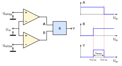
Each single comparator detects the common input voltage against one of two reference voltages, normally upper and lower limits.[3] Outputs behind a logic gate like AND detect the input as in range of the so-called "window" between upper and lower reference.
Window detectors are used in industrial alarms, level sensor and controls, digital computers and production-line testing.
Function
| Uin | A | B | Y |
|---|---|---|---|
| > Urefbot | 0 | 1 | 0 |
| < Ureftop | 1 | 0 | 0 |
| < Ureftop > Urefbot |
1 | 1 | 1 |
If Uin is greater than Urefbot and Uin is lower than Ureftop then both comparators output will swing to the logical high and make the AND gate output to turn ON.
See also
References
- Ram?n Pall?s-Areny; John G. Webster (1999). Analog Signal Processing. John Wiley & Sons. pp. 287–. ISBN 978-0-471-12528-0.
- Bali (2008). Linear Integrated Circuits. Tata McGraw-Hill Education. pp. 155–. ISBN 978-0-07-064807-4.
- Steve Ciarcia (1990). Ciarcia's Circuit Cellar. Circuit Cellar. pp. 1–. ISBN 978-0-07-010969-8.
Further reading
- Tietze, Ulrich; Schenk, Christoph (1993). Halbleiter-Schaltungstechnik (10th ed.). Springer. pp. 190–191. ISBN 3-540-56184-6.