Regency TR-1
The Regency TR-1 was the first commercially manufactured transistor radio. First sold in 1954, it was a novelty due to small size and portability; about 150,000 units were sold despite mediocre performance. The device demonstrated the use of transistors for consumer electronics; previously transistors had only been used in military or industrial applications. Surviving specimens are sought out by collectors.
History
Two companies—Texas Instruments of Dallas, Texas, and Industrial Development Engineering Associates (I.D.E.A.) founded by Joseph B. Weaver of Fishers, Indiana—worked together to produce the Regency TR-1. Previously, Texas Instruments produced instrumentation for the oil industry and locating devices for the U.S. Navy—and I.D.E.A. built home television antenna boosters. The two companies worked together on the TR-1 to grow revenues for their respective companies by pioneering this new product area.[1]
In May 1954, Texas Instruments was looking for an established radio manufacturer to develop and market a radio using their transistors. No major radio maker, including RCA, Philco, and Emerson, was interested. The President of I.D.E.A. at the time, Ed Tudor, jumped at the opportunity to manufacture the TR-1, predicting sales of the transistor radios would be "20 million radios in three years."[2] The Regency Division of I.D.E.A announced the TR-1 on October 18, 1954, and put it on sale in November 1954. It was the first practical transistor radio made in significant numbers.
One year after the TR-1 release, sales approached 100,000 units. The look and size of the TR-1 were well received, but reviews of its performance were typically adverse.[3] The Regency TR-1 is patented by Richard C. Koch, US 2892931, former Project Engineer of I.D.E.A.[4].
The Regency TR-1 circuitry was refined from the Texas Instruments drawings, reducing the number of parts, including two expensive transistors. Though this severely reduced the audio output volume, it let I.D.E.A. sell the radio for only a small profit. The initial TR-1 retail price was $49.95 (roughly $443 in year-2016 dollars) and it sold about 150,000 units[5].
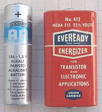
The TR-1 uses Texas Instruments' NPN transistors, hand-picked in sets of four. A 22.5 volt battery provides power, since the only way to get adequate radio frequency performance out of early transistors was to run them close to their collector-to-emitter breakdown voltage. The current drain from this battery is only 4 mA,[6] allowing 20 to 30 hours of operation, in comparison to only several hours for the portable receivers based on vacuum tubes.[7]
While the radio was praised for novelty and small size, the sensitivity and sound quality were behind the tube-based competitors. A review in Consumer Reports mentions the high level of noise and instability on certain radio frequencies, recommending against the purchase.[7]
Design
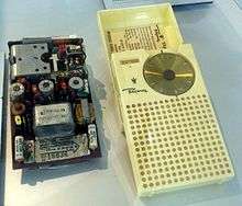
I.D.E.A. outsourced the TR-1 exterior design to the industrial design firm of Painter, Teague and Petertil. The design was created within six weeks by way of telephone and design sketches exchanged by mail. The design won an award from the Industrial Design Society of New York and was selected by the Museum of Modern Art for the American Art and Design Exhibition in Paris in 1955.[8]
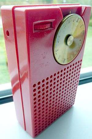
The TR-1 was initially offered in black, bone white, mandarin red, and cloud gray. It was later uncommonly offered in olive green and mahogany. Other later, rare colors included lavender, pearl white, turquoise, pink, and lime. It was advertised as being 3" x 5" x 1.25" and weighed 12 ounces including the 22.5 volt battery. It came in a cardboard box with the color stamped on the end. An optional earphone sold for $7.50.[9]
The red triangles on the frequency dial mark the CONELRAD frequencies of 640 and 1240 kHz.
Circuit
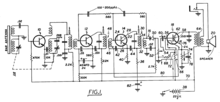
The TR-1 is a superheterodyne receiver made[10] with four n-p-n germanium transistors and one diode. It contains a single transistor converter stage, followed by two intermediate-frequency amplifier stages. After detection, a single-transistor stage amplifies the audio frequency. All amplifier stages use common emitter amplifiers. Stages are transformer coupled, with tuned transformers for the intermediate frequency amplifiers and a miniature audio transformer for the loudspeaker. The intermediate frequency transformers are paired with capacitors, and hand tuned to the intermediate frequency (262 kHz[6]) using movable cores.
The circuit was designed so as to get the maximum possible gain out of the first three transistors (which operated at radio frequencies). The first transistor used as a frequency converter was operated very close to its VCBO of 30 volts (from the 22.5 volt battery). This gives a larger depletion layer between the collector and the base which reduces the parasitic feedback due to the Miller effect and extends the frequency range. The two intermediate frequency amplifier transistors are neutralised to cancel out their parasitic Miller effect feedback which also extends their frequency range. Replacement transistors were supplied with the correct neutralising capacitor of 100-200 pF.
The receiver has automatic gain control. The DC level of the detected signal is filtered with a large capacitor and used to control the gain of the first IF stage.[11]
The 22.5 V battery, while now uncommon, is still used in some devices and as of 2019 remains available on the market.[12] The minimum required voltage is lower, about 15 V, below which the radio oscillates. An electrolytic capacitor is connected in parallel to the battery to improves stability. The power switch is coupled with the volume control.
Manufacture
Regency began manufacturing the TR-1 on October 25, 1954. The manufacture was a collective effort by manufacturers around the country. The transistors and transformers came from Texas Instruments in Dallas. Capacitors came from International Electronics, Inc. of Nashville,[1] Erie Electronics of Erie, Pennsylvania, and Centralab of Milwaukee, Wisconsin. The speakers came from Jensen in Chicago, Illinois. IF transformers came from Vokar of Dexter, Michigan. The volume control came from the Chicago Telephone Supply in Elkhart, Indiana. The tuning capacitor came from Radio Condenser Co. in Camden, New Jersey. The Richardson Company in Melrose Park, Illinois and Indianapolis supplied the circuit board material to Joseph B. Weaver, founder of Photos by Weaver/I.D.E.A./Regency Electronics/Printed Writing, Inc., that manufactured the first circuit board in the basement of his home in Fishers, IN. The actual plastic case for the TR-1 was produced by Argus Plastics in Indianapolis, Indiana.[9]
References
- Smicoe, Robert J. "The Revolution in Your Pocket". Invention & Technology Magazine, Fall 2004, Volume 20, Issue 2. Archived from the original on 2006. Retrieved April 20, 2010.
- David Lane & Robert Lane (1994). Transistor Radios: A Collector's Encyclopedia and Price Guide. Wallace-Homestead Book Company. ISBN 0-87069-712-9. page 3
- David Lane & Robert Lane (1994). Transistor Radios: A Collector's Encyclopedia and Price Guide. Wallace-Homestead Book Company. ISBN 0-87069-712-9. page 4
- Pies, Don (1998). "Regency TR-1 Transistor Radio History". Retrieved February 19, 2019.
Regency's master engineer, Dick Koch
- Pies, Don (1998). "Regency TR-1 Transistor Radio History". Retrieved February 19, 2019.
and 140,000 TR-1's poured off the production line
- TR-1, The First Transistor Radio Receiver. Technical Data And Service Notes. — Regency Div. I.D.E.A. Inc., Indianapolis, Ind., P. 2 Archived May 6, 2005, at the Wayback Machine
- Schiffer, M. B. The portable radio in American life. — University of Arizona Press, 1991. — P. 170–178. — 259 p. — ISBN 9780816512843
- Handy, Erbe, Blackham, Antonier (1993). Made In Japan : Transistor Radios of the 1950s and 1960s. Chronicle Books. ISBN 0-8118-0271-X.CS1 maint: multiple names: authors list (link) pages 15–17
- Reyer, Steve (Dr.) "Regency TR-1 Transistor Radio Facts and Figures". Retrieved December 2, 2012
- Regency schematic
- Lee, T. C. The Design of CMOS Radio-Frequency Integrated Circuits. — Cambridge University Press, 2004. — P. 271–272. — 797 p. — ISBN 9780521835398
- "Eveready 412 Carbon Zinc 22.5V Battery NEDA 215, 15F20, BLR122". Batteriesinaflash.com.
External links
| Wikimedia Commons has media related to Regency TR-1. |
- Schematic of Regency TR-1
- Regency TR-1 Transistor Radio History: Web site with many historical references on the web and in published literature