Piston motion equations
The motion of a non-offset piston connected to a crank through a connecting rod (as would be found in internal combustion engines), can be expressed through several mathematical equations. This article shows how these motion equations are derived, and shows an example graph.
Crankshaft geometry
Definitions
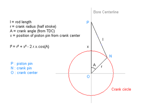
- rod length (distance between piston pin and crank pin)
- crank radius (distance between crank pin and crank center, i.e. half stroke)
- crank angle (from cylinder bore centerline at TDC)
- piston pin position (upward from crank center along cylinder bore centerline)
- piston pin velocity (upward from crank center along cylinder bore centerline)
- piston pin acceleration (upward from crank center along cylinder bore centerline)
- crank angular velocity


″Angular velocity″
The crankshaft angular velocity is related to the engine revolutions per minute (RPM):

Triangle relation
As shown in the diagram, the crank pin, crank center and piston pin form triangle NOP.
By the cosine law it is seen that:

Equations with respect to angular position (Angle Domain)
The equations that follow describe the reciprocating motion of the piston with respect to crank angle.
Example graphs of these equations are shown below.
Position
Position with respect to crank angle (by rearranging the triangle relation):


Velocity
Velocity with respect to crank angle (take first derivative, using the chain rule):
- Velocity is negative when x decreases with time(A < 180 degrees) and is positive when x increases with time(A > 180 degrees). The magnitude of the second term is always less than rsinA and hence does not affect the sign (as l>= 2*r).

Acceleration
Acceleration with respect to crank angle (take second derivative, using the chain rule and the quotient rule):

Equations with respect to time (time domain)
Angular velocity derivatives
If angular velocity is constant, then

and the following relations apply:


Converting from angle domain to time domain
The equations that follow describe the reciprocating motion of the piston with respect to time. If time domain is required instead of angle domain, first replace A with ωt in the equations, and then scale for angular velocity as follows:
Position
Position with respect to time is simply:


Acceleration
Acceleration with respect to time (using the chain rule and product rule, and the angular velocity derivatives):

Scaling for angular velocity
You can see that x is unscaled, x' is scaled by ω, and x" is scaled by ω². To convert x' from velocity vs angle [inch/rad] to velocity vs time [inch/s] multiply x' by ω [rad/s]. To convert x" from acceleration vs angle [inch/rad²] to acceleration vs time [inch/s²] multiply x" by ω² [rad²/s²]. Note that dimensional analysis shows that the units are consistent.
Velocity maxima/minima
Acceleration zero crossings
The velocity maxima and minima do not occur at crank angles (A) of plus or minus 90°. The velocity maxima and minima occur at crank angles that depend on rod length (l) and half stroke (r), and correspond to the crank angles where the acceleration is zero (crossing the horizontal axis).
Crank-rod angle not right angled
The velocity maxima and minima do not necessarily occur when the crank makes a right angle with the rod. Counter-examples exist to disprove the idea that velocity maxima/minima occur when crank-rod angle is right angled.
Example
For rod length 6" and crank radius 2", numerically solving the acceleration zero-crossings finds the velocity maxima/minima to be at crank angles of ±73.17615°. Then, using the triangle sine law, it is found that the crank-rod angle is 88.21738° and the rod-vertical angle is 18.60647°. Clearly, in this example, the angle between the crank and the rod is not a right angle. Summing the angles of the triangle 88.21738° + 18.60647° + 73.17615° gives 180.00000°. A single counter-example is sufficient to disprove the statement "velocity maxima/minima occur when crank makes a right angle with rod".
Example graph of piston motion
The graph shows x, x', x" with respect to crank angle for various half strokes, where L = rod length (l) and R = half stroke (r):

Pistons motion animation with same rod length and crank radius values in graph above :
Further reading
- John Benjamin Heywood, Internal Combustion Engine Fundamentals, McGraw Hill, 1989.
- Charles Fayette Taylor, The Internal Combustion Engine in Theory and Practice, Vol. 1 & 2, 2nd Edition, MIT Press 1985.