Non-return-to-zero
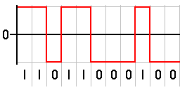
In telecommunication, a non-return-to-zero (NRZ) line code is a binary code in which ones are represented by one significant condition, usually a positive voltage, while zeros are represented by some other significant condition, usually a negative voltage, with no other neutral or rest condition. The pulses in NRZ have more energy than a return-to-zero (RZ) code, which also has an additional rest state beside the conditions for ones and zeros. NRZ is not inherently a self-clocking signal, so some additional synchronization technique must be used for avoiding bit slips; examples of such techniques are a run-length-limited constraint and a parallel synchronization signal.
For a given data signaling rate, i.e., bit rate, the NRZ code requires only half the baseband bandwidth required by the Manchester code (the passband bandwidth is the same). When used to represent data in an asynchronous communication scheme, the absence of a neutral state requires other mechanisms for bit synchronization when a separate clock signal is not available.
NRZ-level itself is not a synchronous system but rather an encoding that can be used in either a synchronous or asynchronous transmission environment, that is, with or without an explicit clock signal involved. Because of this, it is not strictly necessary to discuss how the NRZ-level encoding acts "on a clock edge" or "during a clock cycle", since all transitions happen in the given amount of time representing the actual or implied integral clock cycle. The real question is that of sampling—the high or low state will be received correctly provided the transmission line has stabilized for that bit when the physical line level is sampled at the receiving end.
However, it is helpful to see NRZ transitions as happening on the trailing (falling) clock edge in order to compare NRZ-level to other encoding methods, such as the mentioned Manchester code, which requires clock edge information (is the XOR of the clock and NRZ, actually) see the difference between NRZ-mark and NRZ-inverted.
Variants
NRZ can refer to any of the following serializer line codes:
| Code name | Alternate name | Complete name | Description |
|---|---|---|---|
| NRZ(L) | NRZL | Non-return-to-zero level | Appears as raw binary bits without any coding. Typically binary 1 maps to logic-level high, and binary 0 maps to logic-level low. Inverse logic mapping is also a type of NRZ(L) code. |
| NRZ(I) | NRZI | Non-return-to-zero inverted | Refers to either an NRZ(M) or NRZ(S) code. |
| NRZ(M) | NRZM | Non-return-to-zero mark | Serializer mapping {0: constant, 1: toggle}. |
| NRZ(S) | NRZS | Non-return-to-zero space | Serializer mapping {0: toggle, 1: constant}. |
| NRZ(C) | NRZC | Non-return-to-zero change |
The NRZ code also can be classified as a polar or non-polar, where polar refers to a mapping to voltages of +V and −V, and non-polar refers to a voltage mapping of +V and 0, for the corresponding binary values of 0 and 1.
Unipolar non-return-to-zero level
"One" is represented by a DC bias on the transmission line (conventionally positive), while "zero" is represented by the absence of bias – the line at 0 volts or grounded. For this reason it is also known as "on-off keying". In clock language, a "one" transitions to or remains at a biased level on the trailing clock edge of the previous bit, while "zero" transitions to or remains at no bias on the trailing clock edge of the previous bit. Among the disadvantages of unipolar NRZ is that it allows for long series without change, which makes synchronization difficult, although this is not unique to the unipolar case. One solution is to not send bytes without transitions. More critically, and unique to unipolar NRZ, are issues related to the presence of a transmitted DC level – the power spectrum of the transmitted signal does not approach zero at zero frequency. This leads to two significant problems: first, the transmitted DC power leads to higher power losses than other encodings, and second, the presence of a DC signal component requires that the transmission line be DC-coupled.
Bipolar non-return-to-zero level
"One" is represented by one physical level (usually a positive voltage), while "zero" is represented by another level (usually a negative voltage). In clock language, in bipolar NRZ-level the voltage "swings" from positive to negative on the trailing edge of the previous bit clock cycle.
An example of this is RS-232, where "one" is −12 V to −5 V and "zero" is +5 V to +12 V.
Non-return-to-zero space
"One" is represented by no change in physical level, while "zero" is represented by a change in physical level. In clock language, the level transitions on the trailing clock edge of the previous bit to represent a "zero".
This "change-on-zero" is used by High-Level Data Link Control and USB. They both avoid long periods of no transitions (even when the data contains long sequences of 1 bits) by using zero-bit insertion. HDLC transmitters insert a 0 bit after 5 contiguous 1 bits (except when transmitting the frame delimiter "01111110"). USB transmitters insert a 0 bit after 6 consecutive 1 bits. The receiver at the far end uses every transition — both from 0 bits in the data and these extra non-data 0 bits — to maintain clock synchronization. The receiver otherwise ignores these non-data 0 bits.
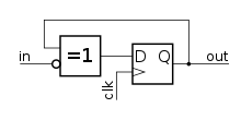
Non-return-to-zero inverted
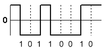

Non-return-to-zero, inverted (NRZI, also known as Nonreturn to Zero IBM[1], Inhibit code[2] or IBM code[2]) was devised by Bryon E. Phelps (IBM) in 1956.[2][3] It is a method of mapping a binary signal to a physical signal for transmission over some transmission medium. The two-level NRZI signal distinguishes data bits by the presence or absence of a transition at a clock boundary.
Which bit value corresponds to a transition varies in practice, and the name NRZI is used for both. Run-length limited (RLL) codes are generally described using the convention that a logical 1 is transmitted as a transition, and a logical 0 is transmitted as no transition. The HDLC and Universal Serial Bus protocols use the opposite convention: a logical 0 is transmitted as a transition, and a logical 1 is transmitted as no transition.
A long series of no-transition bits can be difficult for a receiver to count accurately, so some means for forcing a transition at reasonable intervals is generally used in addition to NRZI. Magnetic disk and tape storage devices generally use fixed-rate RLL codes, while HDLC and USB use bit stuffing: they insert an additional 0 bit (forcing a transition) after 5 or 6 (respectively) consecutive 1 bits. While bit stuffing is efficient, it results in a variable data rate because it takes slightly longer to send a long string of 1 bits than it does to send a long string of 0 bits.
Synchronized NRZI (NRZI-S, SNRZI) and group-coded recording (GCR) are modified forms of NRZI.[4] In NRZI-S, each 8-bit group is extended to 9 bits by a 1 in order to establish a transition for synchronisation.[4]
Randomized non-return-to-zero
Return-to-zero describes a line code used in telecommunications signals in which the signal drops (returns) to zero between each pulse. This takes place even if a number of consecutive 0s or 1s occur in the signal. The signal is self-clocking. This means that a separate clock does not need to be sent alongside the signal, but suffers from using twice the bandwidth to achieve the same data-rate as compared to non-return-to-zero format.
The "zero" between each bit is a neutral or rest condition, such as a zero amplitude in pulse amplitude modulation (PAM), zero phase shift in phase-shift keying (PSK), or mid-frequency in frequency-shift keying (FSK). That "zero" condition is typically halfway between the significant condition representing a 1 bit and the other significant condition representing a 0 bit.
Although return-to-zero contains a provision for synchronization, it still has a DC component resulting in “baseline wander” during long strings of 0 or 1 bits, just like the line code non-return-to-zero.
See also
| Wikimedia Commons has media related to Non return to zero. |
- Bipolar encoding
- Enhanced non-return-to-zero-Level E-NRZ-L
- Return-to-zero
- Line code
- Universal asynchronous receiver/transmitter
- Manchester code
References
- IBM 729 II, IV, V, VI Magnetic Tape Units (PDF) (223-6988 ed.). 1962. p. 7. Retrieved 12 February 2018.
- Palmer, Dean (2005). "Section 1: Recording Systems, 1: A brief history of magnetic recording". In Vasic, Bane; Kurtas, Erozan M. (eds.). Coding and Signal Processing for Magnetic Recording Systems (1st ed.). CRC Press LLC. pp. I-6, I-15. ISBN 0-8493-1524-7.
- US 2774646, Phelps, Bryon E., "Magnetic recording method", published 1956-12-18, assigned to IBM (See also: DE950858C)
- Patel, Arvind Motibhai (1988). "5. Signal and Error-Control Coding". In Mee, C. Denis; Daniel, Eric D. (eds.). Magnetic Recording. II: Computer Data Storage (1st ed.). McGraw-Hill Book Company. ISBN 0-07-041272-3.
Further reading
- Brey, Barry. The Intel Microprocessors. Columbus: Pearson Prentice Hall. ISBN 0-13-119506-9.
- Savard, John J. G. (2018) [2006]. "Digital Magnetic Tape Recording". quadibloc. Archived from the original on 2018-07-02. Retrieved 2018-07-16.
![]()
Line coding (digital baseband transmission) | ||
|---|---|---|
| Main articles |
|  |
| Basic line codes | ||
| Extended line codes |
| |
| Optical line codes |
| |
| ||