Nanogenerator
A Nanogenerator is a type of technology that converts mechanical/thermal energy as produced by small-scale physical change into electricity. A Nanogenerator has three typical approaches: piezoelectric, triboelectric, and pyroelectric nanogenerators. Both the piezoelectric and triboelectric nanogenerators can convert mechanical energy into electricity. However, pyroelectric nanogenerators can be used to harvest thermal energy from a time-dependent temperature fluctuation.
Nanogenerators are referred as a field that uses displacement current as the driving force for effectively converting mechanical energy into electric power/signal, disregarding if nanomaterials are used or not.[1]
Theory of nanogenerators from Maxwell's equations
Maxwell's equations, which are among the top 10 most important equations for physics, have the following basic forms:
(1.1)

(1.2)

(1.3)

(1.4)

where the displacement current, , was first introduced by Maxwell in 1861 to satisfy the continuity equation for electric charges.[2] The electric displacement vector D is given by , and for an isotropic dielectric medium, , thus . The displacement current density is presented as


(2.1)

Recently, the Maxwell's equations have been expanded to calculate the power output of nanogenerators. An additional term Ps was first added into D by Wang in 2017,[3][4] where Ps is the polarization created by the electrostatic surface charges owing to mechanical triggering, different from the electric field induced medium polarization P. The D can be rewritten as , so the displacement current density is obtained by

(2.2)

Then the Maxwell's equations can be expanded as[1]
(3.1)

(3.2)
(3.3)
(3.4)

These equations are the cornerstones for deriving the output characteristics of nanogenerators, from which the output current and voltage, and the related electromagnetic radiation of a nanogenerator have all been derived.
General theory for the polarization Ps
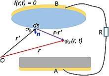
The polarization Ps created by the electrostatic surface charges can be expressed by the following equation, when defining the charge density function σs(r,t) on the media surface by a shape function of f(r,t)=0.
(4)

where the delta function δ(f(r,t)) is introduced to confine the media shape. Through solving the scalar electric potential from the surface charges

(5)

the Ps can be obtained by[1]
(6)

This is the general expression of the surface polarization density Ps in Eq. (3.1) and (3.4).
Current transport equation for nanogenerators
The displacement current is obtained by a surface integral of JD
(7)

where Q is the total free charge amount on the electrode. In the nanogenerators, the displacement current dominates the internal circuit, while the capacitive conduction current dominates the external circuit.
The current transport behavior of any configuration of nanogenerators can be derived by the following general equation[1]
(8)
where is the potential drop from A electrode to B electrode (Fig. 1), and integral dL is over a path from point A to point B.


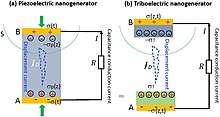
The current transport equation for a piezoelectric nanogenerator (Fig. 2a) is
(9)

where A is the electrode area, z is the piezoelectric film thickness, and σp is the polarization charge density.
The current transport equation for the triboelectric nanogenerator in the contact-separation mode (Fig. 2b) is
(10)

where H(t) is a function dependent on the contacting rate between the two dielectrics. Based on the transport equation, the displacement current, electric potential, output current and output power can be calculated for four basic TENG modes.
Technology projections from Maxwell's displacement current
The first term of the displacement current proposed by Maxwell gives the birth of electromagnetic wave theory, and the electromagnetic induction causes the emergence of antenna, radio, telegram, TV, Radar, microwave, wireless communication, and space technology. The electromagnetic unification produces the theory of light, laying the theorerical foundation for the invention of laser and development of photonics. The first component has driven the world development in communication and laser technology in the last century. The second term first proposed by Wang[4] set the foundation for the nanogenerators. Adding a term of in the displacement current and thus in the Maxwell's equations extends their applications to energy! The nanogenerators are another important applications of Maxwell's equations to energy and sensors after the electromagnetic wave theory and technology.


Piezoelectric nanogenerator
A piezoelectric nanogenerator is an energy harvesting device capable of converting external kinetic energy into electrical energy via action by a nano-structured piezoelectric material. Although its definition may include any types of energy harvesting devices using nano-structures to convert various types of ambient energy (e.g. solar power and thermal energy), it is generally used to indicate kinetic energy harvesting devices utilizing nano-scaled piezoelectric material since its first introduction in 2006.[5]
Although still in the early stages of development, the technology has been regarded as a potential breakthrough toward further miniaturization of conventional energy harvesters, possibly leading to facile integration with other types of energy harvesters and the independent operation of mobile electronic devices with reduced concern for sources of energy.
Mechanism

The working principle of nanogenerator will be explained for 2 different cases: the force exerted perpendicular and parallel to the axis of the nanowire.
The working principle for the first case is explained by a vertically grown nanowire subjected to the laterally moving tip. When a piezoelectric structure is subjected to the external force by the moving tip, the deformation occurs throughout the structure. The piezoelectric effect will create the electrical field inside the nanostructure; the stretched part with the positive strain will exhibit the positive electrical potential, whereas the compressed part with the negative strain will show the negative electrical potential. This is due to the relative displacement of cations with respect to anions in its crystalline structure. As a result, the tip of the nanowire will have an electrical potential distribution on its surface, while the bottom of the nanowire is neutralized since it is grounded. The maximum voltage generated in the nanowire can be calculated by the following equation:[6]

, where κ0 is the permittivity in vacuum, κ is the dielectric constant, e33, e15 and e31 are the piezoelectric coefficients, ν is the Poisson ratio, a is the radius of the nanowire, l is the length of the nanowire and νmax is the maximum deflection of the nanowire's tip.
The electrical contact plays an important role to pump out charges in the surface of the tip. The schottky contact must be formed between the counter electrode and the tip of the nanowire since the ohmic contact will neutralize the electrical field generated at the tip. In order to form an effective schottky contact, the electron affinity(Ea) must be smaller than the work function(φ) of the metal composing the counter electrode. For the case of ZnO nanowire with the electron affinity of 4.5 eV, Pt (φ=6.1eV) is a suitable metal to construct the schottky contact. By constructing the schottky contact, the electrons will pass to the counter electrode from the surface of the tip when the counter electrode is in contact with the regions of the negative potential, whereas no current will be generated when it is in contact with the regions of the positive potential, in the case of n-type semiconductive nanostructure (p-type semiconductive structure will exhibit the reversed phenomenon since the hole is mobile in this case). The formation of the schottky contact also contributes to the generation of direct current output signal consequently.
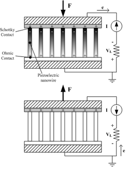
For the second case, a model with a vertically grown nanowire stacked between the ohmic contact at its bottom and the schottky contact at its top is considered. When the force is applied toward the tip of the nanowire, the uniaxial compressive is generated in the nanowire. Due to the piezoelectric effect, the tip of the nanowire will have a negative piezoelectric potential, increasing the Fermi level at the tip. Since the electrons will then flow from the tip to the bottom through the external circuit as a result, the positive electrical potential will be generated at the tip. The schottky contact will barricade the electrons being transported through the interface, therefore maintaining the potential at the tip. As the force is removed, the piezoelectric effect diminishes, and the electrons will be flowing back to the top in order to neutralize the positive potential at the tip. The second case will generate alternating current output signal.
Geometrical configuration
Depending on the configuration of piezoelectric nanostructure, the most of the nanogenerator can be categorized into 3 types: VING, LING and "NEG". Still, there is a configuration that do not fall into the aforementioned categories, as stated in other type.
Vertical nanowire Integrated Nanogenerator (VING).
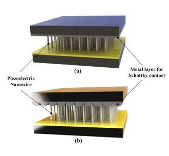
VING is a 3-dimensional configuration consisting of a stack of 3 layers in general, which are the base electrode, the vertically grown piezoelectric nanostructure and the counter electrode. The piezoelectric nanostructure is usually grown from the base electrode by various synthesizing techniques, which are then integrated with the counter electrode in full or partial mechanical contact with its tip.
After Professor Zhong Lin Wang of the Georgia Institute of Technology has introduced a basic configuration of VING in 2006 where he used a tip of atomic force microscope (AFM) to induce the deformation of a single vertical ZnO nanowire, the first development of VING is followed in 2007.[7] The first VING utilizes the counter electrode with the periodic surface grating resembling the arrays of AFM tip as a moving electrode. Since the counter electrode is not in full contact with the tips of the piezoelectric nanowire, its motion in-plane or out-of-plane occurred by the external vibration induces the deformation of the piezoelectric nanostructure, leading to the generation of the electrical potential distribution inside each individual nanowire. The counter electrode is coated with the metal forming the schottky contact with the tip of the nanowire, where only the compressed portion of piezoelectric nanowire would allow the accumulated electrons pass through the barrier between its tip and the counter electrode, in case of n-type nanowire. The switch-on and –off characteristic of this configuration shows its capability of generating direct current generation without any requirement for the external rectifier.
In VING with partial contact, the geometry of the counter electrode plays an important role. The flat counter electrode would not induce the sufficient deformation of the piezoelectric nanostructures, especially when the counter electrode moves by in-plane mode. After the basic geometry resembling the array of AFM tips, a few other approaches have been followed for facile development of the counter electrode. Professor Zhong Lin Wang's group have generated counter electrode composed of ZnO nanorods utilizing the similar technique used for synthesizing ZnO nanowire array. Professor Sang-Woo Kim's group of Sungkyunkwan University (SKKU) and Dr. Jae-Young Choi's group of Samsung Advanced Institute of Technology (SAIT) in South Korea introduced bowl-shaped transparent counter electrode by combining anodized aluminum and the electroplating technology.[8] They also have developed the other type of the counter electrode by using networked single-walled carbon-nanotube (SWNT) on the flexible substrate, which is not only effective for energy conversion but also transparent.[9]
The other type of VING has been also suggested. While it shares the identical geometric configuration with the aforementioned, such a VING has full mechanical contact between the tips of the nanowires and the counter electrode.[10] This configuration is effective for application where the force is exerted in the vertical direction (toward the c axis of the piezoelectric nanowire), and it generates alternating current (AC) unlike VINGs with partial contact.
Lateral nanowire Integrated Nanogenerator (LING).

LING is a 2-dimensional configuration consisting of three parts: the base electrode, the laterally grown piezoelectric nanostructure and the metal electrode for schottky contact. In most of cases, the thickness of the substrate film is much thicker than the diameter of the piezoelectric nanostructure, so the individual nanostructure is subjected to the pure tensile strain.
LING is an expansion of single wire generator (SWG), where a laterally aligned nanowire is integrated on the flexible substrate. SWG is rather a scientific configuration used for verifying the capability of electrical energy generation of a piezoelectric material and is widely adopted in the early stage of the development.
As of VINGs with full mechanical contact, LING generates AC electrical signal. The output voltage can be amplified by constructing an array of LING connected in series on the single substrate, leading the constructive addition of the output voltage. Such a configuration may lead to the practical application of LING for scavenging large-scale power, for example, wind or ocean waves.
Nanocomposite Electrical Generators (NEG).
"NEG" is a 3-dimensional configuration consisting three main parts: the metal plate electrodes, the vertically grown piezoelectric nanostructure and the polymer matrix which fills in between in the piezoelectric nanostructure.
NEG was introduced by Momeni et al.[11] It was shown that NEG has a higher efficiency compared to original nanogenerator configuration which a ZnO nanowire will be bended by an AFM tip. It is also shown that it provides an energy source with higher sustainability.
Other type. The fabric-like geometrical configuration has been suggested by Professor Zhong Lin Wang in 2008. The piezoelectric nanowire is grown vertically on the two microfibers in its radial direction, and they are twined to form a nanogenerator.[12] One of the microfibers is coated with the metal to form a schottky contact, serving as the counter electrode of VINGs. As the movable microfiber is stretched, the deformation of the nanostructure occurs on the stationary microfiber, resulting in the voltage generation. Its working principle is identical to VINGs with partial mechanical contact, thus generating DC electrical signal.
Materials
Among various piezoelectric materials studied for the nanogenerator, many of the researches have been focused on the materials with wurtzite structure such as ZnO, CdS[13] and GaN.[14] The greatest advantage of these material arises from the facile and cost-effective fabrication technique, hydrothermal synthesis. Since the hydrothermal synthesis can be conducted in a low temperature environment under 100 °C in addition to vertical and crystalline growth, these materials can be integrated in various substrates with reduced concern for its physical characteristics such as a melting temperature.
Endeavors for enhancing the piezoelectricity of the individual nanowire also led to the development of other piezoelectric materials based on Wurtzite structure. Professor Zhong Lin Wang of Georgia Institute of Technology introduced p-type ZnO nanowire.[15] Unlike the n-type semiconductive nanostructure, the mobile particle in p-type is a hole, thus the schottky behavior is reversed from that of n-type case; the electrical signal is generated from the portion of the nanostructure where the holes are accumulated. It is experimentally proved that p-type ZnO nanowire can generate the output signal near 10 times that of n-type ZnO nanowire.
From the idea that the material with perovskite structure is known to have more effective piezoelectric characteristic compared to that with wurtzite structure, Barium titanate (BaTiO3) nanowire has been also studied by Professor Min-Feng Yu of University of Illinois at Urbana Champaign.[16] The output signal is found to be more than 16 time that from a similar ZnO nanowire.
Professor Liwei Lin of University of California, Berkeley has suggested that PVDF can be also applied to form a nanogenerator.[17] Being a polymer, PVDF utilizes a near-field electrospinning for its fabrication, which is rather a different technique compared to other materials. The nanofiber can be directly written on the substrate controlling the process, and this technique is expected to be applied for forming self-powered textile based on nanofiber. Researchers from SUTD presented the successful synthesis of ultra-long potassium niobate (KNbO3) nanofibers using a sol-gel assisted far-field electrospinning process[18] and utilized them to develop a high output voltage flexible nanogenerator.[19]
Considering that the piezoelectric constant plays a critical role in the overall performance of a piezoelectric nanogenerator, another research direction to improve device efficiency is to find new material of large piezoelectric response. Lead Magnesium Niobate-Lead Titanate (PMN-PT) is a next-generation piezoelectric material with super high piezoelectric constant when ideal composition and orientation are obtained. In 2012, PMN-PT Nanowires with a very high piezoelectric constant were fabricated by a hydro-thermal approach[20] and then assembled into an energy-harvesting device.[21] The record-high piezoelectric constant was further improved by the fabrication of a single-crystal PMN-PT nanobelt,[22] which was then used as the essential building block for a piezoelectric nanogenerator.
Comparison of the reported materials by 2010 is given in the following table.
| Material | Type | Geometry | Output voltage | Output power | Synthesis | Researched at |
|---|---|---|---|---|---|---|
| ZnO (n-type) | Wurtzite | D: ~100 nm, L: 200~500 nm | VP=~9 mV @ R=500 MΩ | ~0.5 pW per cycle (estimated) | CVD, hydrothermal process | Georgia Tech. |
| ZnO (p-type) | Wurtzite | D: ~50 nm, L: ~600 nm | VP=50~90 mV @ R=500 MΩ | 5~16.2 pW per cycle (calculated) | CVD | Georgia Tech. |
| ZnO-ZnS | Wurtzite (Heterostructure) | Not stated | VP=~6 mV @ R=500 MΩ | ~0.1 pW per cycle (calculated) | Thermal evaporation and etching | Georgia Tech. |
| GaN | Wurtzite | D: 25~70 nm, L: 10~20 μm | Vavg=~20 mV, Vmax=~0.35 V@ R=500 MΩ | ~0.8 pW per cycle (average, calculated) | CVD | Georgia Tech.[14] |
| CdS | Wurtzite | D: ~100 nm, L: 1 μm | VP=~3 mV | Not stated | PVD, Hydrothermal Process | Georgia Tech.[13] |
| BaTiO3 | Perovskite | D: ~280 nm, L: ~15 μm | VP=~25 mV @ R=100 MΩ | ~0.3 aJ per cycle (stated) | High temperature chemical reaction | UIUC[16] |
| PVDF | Polymer | D: 0.5~6.5 μm, L: 0.1~0.6 mm | VP=5~30 mV | 2.5 pW~90 pW per cycle (calculated) | Electro spinning | UC Berkeley[17] |
| KNbO3 | Perovskite | D: ~100 nm; L: few cm | Vp = ~16 V @ R=100 MΩ | Electro spinning | SUTD/MIT[19] |
Applications
Nanogenerator is expected to be applied for various applications where the periodic kinetic energy exists, such as wind and ocean waves in a large scale to the muscle movement by the beat of a heart or inhalation of lung in a small scale. The further feasible applications are as follows.
Self-powered nano/micro devices. One of the feasible applications of nanogenerator is an independent or a supplementary energy source to nano/micro devices consuming relatively low amount of energy in a condition where the kinetic energy is supplied continuously. One of example has been introduced by Professor Zhong Lin Wang's group in 2010 by the self-powered pH or UV sensor integrated VING with an output voltage of 20~40 mV onto the sensor.
Still, the converted electrical energy is relatively small for operating nano/micro devices; therefore the range of its application is still bounded as a supplementary energy source to the battery. The breakthrough is being sought by combining the nanogenerator with the other types of energy harvesting devices, such as solar cell or biochemical energy harvester.[23][24] This approach is expected to contribute to the development of the energy source suitable for the application where the independent operation is crucial, such as Smartdust.
Smart Wearable Systems. The outfit integrated or made of the textiles with the piezoelectric fiber is one of the feasible applications of the nanogenerator. The kinetic energy from the human body is converted to the electrical energy through the piezoelectric fibers, and it can be possibly applied to supply the portable electronic devices such as health-monitoring system attached with the Smart Wearable Systems. The nanogenerator such as VING can be also easily integrated in the shoe employing the walking motion of human body.
Another similar application is a power-generating artificial skin. Professor Zhong Lin Wang's group has shown the possibility by generating AC voltage of up to 100 mV from the flexible SWG attached to the running hamster.[25]
Transparent and Flexible Devices. Some of the piezoelectric nanostructure can be formed in various kinds of substrates, such as flexible and transparent organic substrate. The research groups in SKKU (Professor Sang-Woo Kim's group) and SAIT (Dr. Jae-Young Choi's group) have developed the transparent and flexible nanogenerator which can be possibly used for self-powered tactile sensor and anticipated that the development may be extended to the energy-efficient touch screen devices. Their research focus is being extended to enhance the transparency of the device and the cost-effectiveness by substituting Indium-Tin-Oxide (ITO) electrode with a graphene layer.[26]
Implantable Telemetric Energy Receiver. The nanogenerator based on ZnO nanowire can be applied for implantable devices since ZnO not only is bio-compatible but also can be synthesized upon the organic substrate, rendering the nanogenerator bio-compatible in overall. The implantable device integrated with the nanogenerator can be operated by receiving the external ultrasonic vibration outside the human body, which is converted to the electrical energy by the piezoelectric nanostructure.
Triboelectric nanogenerator
Overview
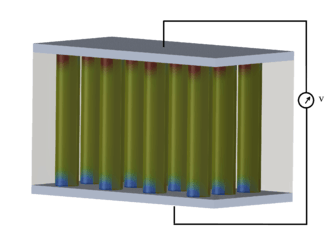
A triboelectric nanogenerator is an energy harvesting device that converts the external mechanical energy into electricity by a conjunction of triboelectric effect and electrostatic induction. This new type of nanogenerator was firstly demonstrated in Prof. Zhong Lin Wang's group at Georgia Institute of Technology in the year of 2012.[27] As for this power generation unit, in the inner circuit, a potential is created by the triboelectric effect due to the charge transfer between two thin organic/inorganic films that exhibit opposite tribo-polarity; in the outer circuit, electrons are driven to flow between two electrodes attached on the back sides of the films in order to balance the potential. Since the most useful materials for TENG are organic, it is also named organic nanogenerator, which is the first of using organic materials for harvesting mechanical energy.
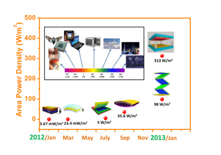
Ever since the first report of the TENG in January 2012, the output power density of TENG has been improved for five orders of magnitude within 12 months. The area power density reaches 313 W/m2, volume density reaches 490 kW/m3, and conversion efficiencies of ~60%[28]–72%[29] have been demonstrated. Besides the unprecedented output performance, this new energy technology also has a number of other advantages, such as low cost in manufacturing and fabrication, excellent robustness and reliability, and environmental friendliness. The triboelectric nanogenerator can be applied to harvest all kind mechanical energy that is available but wasted in our daily life, such as human motion, walking, vibration, mechanical triggering, rotating tire, wind, flowing water and more.[28]
More importantly, Ramakrishna Podila's group at Clemson University demonstrated the first truly wireless triboelectric nanogenerators,[30] which were able to wirelessly charge energy storage devices (e.g., batteries and capacitors) without need for any external amplification and boosters.[31] These wireless generators could possibly pave the way for new systems that could be used to harvest mechanical energy and wirelessly transmit the generated energy for storage.
The triboelectric nanogenerator has three basic operation modes: vertical contact-separation mode, in-plane sliding mode, and single-electrode mode. They have different characteristics and are suitable for different applications.
Basic modes and mechanisms
Vertical Contact-Separation Mode
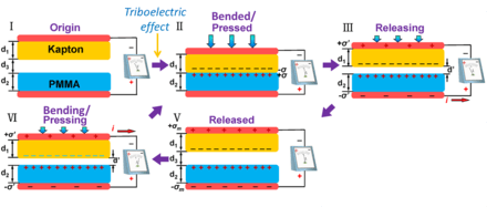
The working mechanism of the triboelectric nanogenerator can be described as the periodic change of the potential difference induced by the cycled separation and re-contact of the opposite triboelectric charges on the inner surfaces of the two sheets. When a mechanical agitation is applied onto the device to bend or press it, the inners surfaces of the two sheets will get into close contact and the charge transfer will begin, leaving one side of the surface with positive charges and the other with negative charges. This is just the triboelectric effect. When the deformation is released, the two surfaces with opposite charges will separate automatically, so that these opposite triboelectric charges will generate an electric field in between and thus induce a potential difference across the top and bottom electrodes. In order to screen this potential difference, the electrons will be driven to flow from one electrode to the other through the external load. The electricity generated in this process will continue until the potentials of the two electrodes get back to even again. Subsequently, when the two sheets are pressed towards each other again, the triboelectric-charge-induced potential difference will begin to decrease to zero, so that the transferred charges will flow back through the external load, to generate another current pulse in the opposite direction. When this periodic mechanical deformation lasts, the alternating current (AC) signals will be continuously generated.[32][33]
As for the pair of materials getting in contact and generating triboelectric charges, at least one of them need to be an insulator, so that the triboelectric charges cannot be conducted away but will remain on the inner surface of the sheet. Then, these immobile triboelectric charges can induce AC electricity flow in the external load under the periodic distance change.
Lateral Sliding Mode
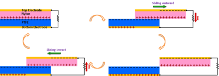
There are two basic friction processes: normal contact, and lateral sliding. We demonstrated here a TENG that is designed based on the in-plane sliding between the two surfaces in lateral direction.[34] With an intensive triboelectrification facilitated by sliding friction, a periodic change in the contact area between two surfaces leads to a lateral separation of the charge centers, which creates a voltage drop for driving the flow of electrons in the external load. The sliding-induced electricity generation mechanism is schematically depicted in the figure. In the original position, the two polymeric surfaces fully overlap and intimately contact with each other. Because of the large difference in the ability to attract electrons, the triboelectrification will leave one surface with net positive charges and the other with net negative charges with equal density. Since the tribo-charges on the insulators will only distribute in the surface layer and will not be leaked out for an extended period of time, the separation between the positively charged surface and negatively charged surface is negligible at this overlapping position, and thus there will be little electric potential drop across the two electrodes. Once the top plate with the positively charged surface starts to slide outward, the in-plane charge separation is initiated due to the decrease in contact surface area. The separated charges will generate an electric field pointing from the right to the left almost parallel to the plates, inducing a higher potential at the top electrode. This potential difference will drive a current flow from the top electrode to the bottom electrode in order to generate an electric potential drop that cancels the tribo-charge-induced potential. Because the vertical distance between the electrode layer and the tribo-charged polymeric surface is negligible compared to the lateral charge separation distance, the amount of the transferred charges on the electrodes approximately equals to the amount of the separated charges at any sliding displacement. Thus, the current flow will continue with the continuation of the ongoing sliding process that keeps increasing the separated charges, until the top plate fully slides out of the bottom plate and the tribo-charged surfaces are entirely separated. The measured current should be determined by the rate at which the two plates are being slid apart. Subsequently, when the top plate is reverted to slide backwards, the separated charges begins to get in contact again but no annihilation due to the insulator nature of the polymer materials. The redundant transferred charges on the electrodes will flow back through the external load with the increase of the contact area, in order to keep the electrostatic equilibrium. This will contribute to a current flow from the bottom electrode to the top electrode, along with the second half cycle of sliding. Once the two plates reach the overlapping position, the charged surfaces get into fully contact again. There will be no transferred charges left on the electrode, and the device returns to the first state. In this entire cycle, the processes of sliding outwards and inwards are symmetric, so a pair of symmetric alternating current peaks should be expected.
The mechanism of in-plane charge separation can work in either one directional sliding between two plates[35] or in rotation mode.[36] In the sliding mode, introducing linear grating or circular segmentation on the sliding surfaces is an extremely efficient means for energy harvesting. With such structures, two patterned triboelectric surfaces can get to fully mismatching position through a displacement of only a grating unit length rather than the entire length of the TENG so that it dramatically increase the transport efficiency of the induced charges.
Single-Electrode Mode
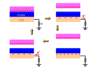
A single-electrode-based triboelectric nanogenerator is introduced as a more practical and feasible design for some applications such as fingertip-driven triboelectric nanoagenerator.[37][38] The working principle of the single-electrode TENG is schematically shown in the figure by the coupling of contact electrification and electrostatic induction. In the original position, the surfaces of skin and PDMS fully contact with each other, resulting in charge transfer between them. According to the triboelectric series, electrons were injected from the skin to the PDMS since the PDMS is more triboelectrically negative than skin, which is the contact electrification process. The produced triboelectric charges with opposite polarities are fully balanced/screened, leading to no electron flow in the external circuit. Once a relative separation between PDMS and skin occurs, these triboelectric charges cannot be compensated. The negative charges on the surface of the PDMS can induce positive charges on the ITO electrode, driving free electrons to flow from the ITO electrode to ground. This electrostatic induction process can give an output voltage/current signal if the distance separating between the touching skin and the bottom PDMS is appreciably comparable to the size of the PDMS film. When negative triboelectric charges on the PDMS are fully screened from the induced positive charges on the ITO electrode by increasing the separation distance between the PDMS and skin, no output signals can be observed, as illustrated. Moreover, when the skin was reverted to approach the PDMS, the induced positive charges on the ITO electrode decrease and the electrons will flow from ground to the ITO electrode until the skin and PDMS fully contact with each other again, resulting in a reversed output voltage/current signal. This is a full cycle of electricity generation process for the TENG in contact-separation mode.
Applications
TENG is a physical process of converting mechanical agitation to an electric signal through the triboelectrification (in inner circuit) and electrostatic induction processes (in outer circuit). This basic process has been demonstrated for two major applications. The first application is energy harvesting with a particular advantage of harvesting mechanical energy. The other application is to serve as a self-powered active sensor, because it does not need an external power source to drive.
- Harvesting vibration energy
Vibrations are a result of the most popular phenomena in society, from walking, voices, engine vibration, automobile, train, aircraft, wind and many more. It exists almost everywhere and at all the time. Harvesting vibration energy is of great value especially for powering mobile electronics, particularly in combination to complementary balanced energy harvesting techniques. Various technologies based on the fundamental principles of triboelectric nanogenerators have been demonstrated for harvesting vibration energy. This application of triboelectric nanogenerator has been demonstrated in the following aspects: 1. Cantilever-based technique is a classical approach for harvesting mechanical energy, especially for MEMS. By designing the contact surface of a cantilever with the top and bottom surfaces during vibration, TENG has been demonstrated for harvesting ambient vibration energy based on the contact-separation mode.[39] 2. To harvest the energy from a backpack, we demonstrated a rationally designed TENG with integrated rhombic gridding, which greatly improved the total current output owing to the structurally multiplied unit cells connected in parallel.[40] 3. With the use of 4 supporting springs, a harmonic resonator-based TENG has been fabricated based on the resonance induced contact-separation between the two triboelectric materials, which has been used to harvest vibration energy from an automobile engin, a sofa and a desk.[41] 4. Recently, a three-dimensional triboelectric nanogenerator (3D-TENG) has been designed based on a hybridization mode of conjunction the vertical contact-separation mode and the in-plane sliding mode.36 The innovative design facilitates harvesting random vibration energy in multiple directions over a wide bandwidth. The 3-D TENG is designed for harvesting ambient vibration energy, especially at low frequencies, under a range of conditions in daily life, thus, opening the applications of TENG in environmental/infrastructure monitoring, charging portable electronics and internet of things.
- Harvesting energy from human body motion
Since there is abundant mechanical energy generated on human bodies in people's everyday life, we can make use of the triboelectric nanogenerator to convert this amount of mechanical energy into electricity, for charging portable electronics and biomedical applications.[42] This will help to greatly improve the convenience of people's life and expand the application of the personal electronics. A packaged power-generating insole with built-in flexible multi-layered triboelectric nanogenerators has been demonstrated, which enable harvesting mechanical pressure during normal walking. The TENG used here relies on the contact-separation mode and is effective in responding to the periodic compression of the insole. Using the insole as a direct power source, we develop a fully packaged self-lighting shoe that has broad applications for display and entertainment purposes. A TENG can be attached to the inner layer of a shirt for harvesting energy from body motion. Under the generally walking, the maximum output of voltage and current density are up to 17 V and 0.02 μA/cm2, respectively. The TENG with a single layer size of 2 cm×7 cm×0.08 cm sticking on the clothes was demonstrated as a sustainable power source that not only can directly light up 30 light-emitting diodes (LEDs), but also can charge a lithium ion battery by persistently clapping clothes.
- Self-powered active strain/force sensors
A triboelectric nanogenerator automatically generates an output voltage and current once it is mechanically triggered. The magnitude or the output signal signifies the impact of the mechanical deformation and its time-dependent behavior. This is the basic principle of the TENG can be applied as a self-powered pressure sensor. The voltage-output signal can reflect the applied pressure induced by a droplet of water. All types of TENGs have a high sensitivity and fast response to the external force and show as a sharp peak signal. Furthermore, the response to the impact of a piece of feather (20 mg, ~0.4 Pa in contact pressure) can be detected. The sensor signal can delicately show these details of the entire process. The existing results show that our sensor can be applied for measuring the subtle pressure in real life.[43]
The active pressure sensor has also been developed in the form of a composite. The term of Triboelectric Composite refers to a sponge-shape polymer with embedded wire. Applying pressure and impact on the composite in any direction causes charge separation between the soft polymer and the active wire because of the presence of composite air gap. Passive wire as the second electrode may be either embedded inside the sponge without any air gap or placed out of the composite allowing the sensor to work in single electrode mode.[44]
In a case that we make a matric array of the triboelectric nanogenerators, a large-area, and self-powered pressure map applied on a surface can be realized.[45] The response of the TENG array with local pressure was measured through a multi-channel measurement system. There are two types of output signals from the TENG: open circuit voltage and short circuit current. The Open circuit voltage is only dictated by the final configuration of the TENG after applying a mechanical triggering, so that it is a measure of the magnitude of the deformation, which is attributed to the static information to be provided by TENG. The output current depends on the rate at which the induced charge would flow, so that the current signal is more sensitive to the dynamic process of how the mechanical triggering is applied.
The active pressure sensor and the integrated sensor array based on the triboelectric effect have several advantages over conventional passive pressure sensors. First, the active sensor is capable of both static pressure sensing using the open-circuit voltage and dynamic pressure sensing using the short-circuit current, while conventional sensors are usually incapable of dynamic sensing to provide the loading rate information. Second, the prompt response of both static and dynamic sensing enables the revealing of details about the loading pressure. Third, the detection limit of the TENG for dynamic sensing is as low as 2.1 Pa, owing to the high output of the TENG. Fourth, the active sensor array presented in this work has no power consumption and could even be combined with its energy harvesting functionality for self-powered pressure mapping. Future works in this field involve the miniaturization of the pixel size to achieve higher spatial resolution, and the integration of the TEAS matrix onto fully flexible substrate for shape-adaptive pressure imaging.
- Self-powered motion sensors
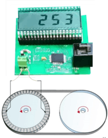
The term of self-powered sensors may reflect far beyond simple voltage-output signal. It can refer to a system which powers all the electronics responsible for measuring and demonstrating the detectable movement. For example, the self-powered triboelectric encoder, integrated in smart belt-pulley system, converts friction into useful electrical energy by storing the harvested energy in a capacitor and fully powering the circuit, including a microcontroller and an LCD.[46]
- Self-powered active chemical sensors
As for triboelectric nanogenerators, maximizing the charge generation on opposite sides can be achieved by selecting the materials with the largest difference in the ability to attract electrons and changing the surface morphology. In such a case, the output of the TENG depends on the type and concentration of molecules adsorbed on the surface of the triboelectric materials, which can be used for fabricating chemical and biochemical sensors. As an example, the performance of the TENG depends on the assembly of Au nanoparticles (NPs) onto the metal plate. These assembled Au NPs not only act as steady gaps between the two plates at strain free condition, but also enable the function of enlarging the contact area of the two plates, which will increase the electrical output of the TENG. Through further modification of 3-mercaptopropionic acid (3-MPA) molecules on the assembled Au NPs, the high-output nanogenerator can become a highly sensitive and selective nanosensor toward Hg2+ ions detection because of the different triboelectric polarity of Au NPs and Hg2+ ions. With its high sensitivity, selectivity and simplicity, the TENG holds great potential for the determination of Hg2+ ions in environmental samples. The TENG is a future sensing system for unreachable and access-denied extreme environments. As different ions, molecules, and materials have their unique triboelectric polarities, we expect that the TENG can become either an electrical turn-on or turn-off sensor when the analytes are selectively binding to the modified electrode surface. We believe this work will serve as the stepping stone for related TENG studies and inspire the development of TENG toward other metal ions and biomolecules such as DNA and proteins in the near future.[47]
Choice of materials and surface structures
Almost all materials known exhibit the triboelectrification effect, from metal, to polymer, to silk and to wood, almost everything. All of these materials can be candidates for fabricating TENGs, so that the materials choices for TENG are huge. However, the ability of a material for gaining/losing electron depends on its polarity. John Carl Wilcke published the first triboelectric series in a 1757 on static charges. A material towards the bottom of the series, when touched to a material near the top of the series, will attain a more negative charge. The further away two materials are from each other on the series, the greater the charge transferred. Beside the choice of the materials in the triboelectric series, the morphologies of the surfaces can be modified by physical techniques with the creation of pyramids-, square- or hemisphere-based micro- or nano-patterns, which are effective for enhancing the contact area and possibly the triboelectrification. However, the created bumpy structure on the surface may increase the friction force, which may possibly reduce the energy conversion efficiency of the TENG. Therefore, an optimization has to be designed for maximizing the conversion efficiency.
The surfaces of the materials can be functionalized chemically using various molecules, nanotubes, nanowires or nanoparticles, in order to enhance the triboelectrification effect. Surface functionalization can largely change the surface potential. The introduction of nanostructures on the surfaces can change the local contact characteristics, which may improve the triboelectrification. This will involve a large amount of studies for testing a range of materials and a range of available nanostructures.
Besides these pure materials, the contact materials can be made of composites, such embedding nanoparticles in polymer matrix. This not only changes the surface electrification, but also the permittivity of the materials so that they can be effective for electrostatic induction. Therefore, there are numerous ways for enhancing the performance of the TENG from the materials point of view. This gives an excellent opportunity for chemists and materials scientists to do extensive study both in the basic science and in practical application. In contrast, materials systems for solar cell and thermal electric, for example, are rather limited, and there are not very many choices for high performance devices.
Standards and Figures-of-Merit
A performance figure-of-merit (FOMP) has been developed to quantitatively evaluate the performance of triboelectric nanogenerators, consisting of a structural figure-of-merit (FOMS) related to the structure of TENG and a material figure-of-merit (FOMM) that is the square of the surface charge density.[48] Considering the breakdown effect, a revised figure-of-merit is also proposed.[49] Based on the FOM, outputs of different TENGs can be compared and evaluated.
- Cycles for energy output of TENG
For a continuous periodic mechanical motion (from displacement x=0 to x=xmax), the electrical output signal from the TENG is also periodically time-dependent. In such a case, the average output power P, which is related to the load resistance, is used to determine the merits of the TENG. Given a certain period of time T, the output energy per cycle E can be derived as:

This indicates that the output energy per cycle E can be calculated as the encircled area of the closed loop in the V–Q curve, and all V-Q cycles are named as ‘cycles for energy output’ (CEO).
- Cycles for maximized energy output of TENG.
By periodic transformation between in load and short circuit conditions, cycles for maximum energy output can be obtained. When the load equals infinite, the V-Q becomes a trapezoid shape, the vertices of which are determined by the maximum short-circuit transferred charge QSC,max, and the maximum output energy can be calculated as:


_of_TENG.jpg)
- Figures-of-merit (FOM) of TENG.
For the TENG operating in CMEO with infinite load resistance, the period T includes two parts of time. One part is from the relative motion in TENG, and the other part is from the discharging process in short-circuit condition. The breakdown effect is widely existing in triboelectric nanogenerators, which will seriously affects the effective maximized energy output, Eem.[50] Therefore, the average output power P at CMEO considering the breakdown effect should satisfy: Where v is the average velocity value of the relative motion in TENG, which depends on the input mechanical motions. In this equation, is the only term that depends on the characteristics of the TENG itself. The energy-conversion efficiency of the TENG can be expressed as (at CMEO with R=∞ considering breakdown effects):


Here F stands for the average dissipative force during the operation of the TENG.[51] This force can be frictional force, air resistance force or others. stands for the average dissipative force during the operation of the TENG. This force can be frictional force, air resistance force or others. Therefore, it can be concluded that the term determines both the average power and the energy-conversion efficiency from the characteristics of TENG itself. Eem contains QSC,max that is proportional to the triboelectrification area A. Therefore, to exclude the effect of the TENG size on the output energy, the area A should be placed in denominator of this term and then the term determines the merits of TENG. QSC,max, VOC,max and V max’ are all proportional to the surface charge density σ. Therefore, Eem is proportional to the square of the surface charge density σ. Then, a dimensionless structural FOM (FOMS) of TENG can be defined, as the factor only depends on the structural parameters and xmax: Here ε0 is the permittivity of the vacuum. This structural FOM represents the merit of the TENG from the structural design. And then the performance FOM (FOMP) of TENG can be defined as: Here, which is the only component related to the material properties. The FOMP can be considered as the universal standard to evaluate varieties of TENGs, since it is directly proportional to the greatest possible average output power and related to the highest achievable energy-conversion efficiency, regardless of the mode and the size of the TENG.


Standardized Method for Output Capacity Assessment
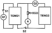
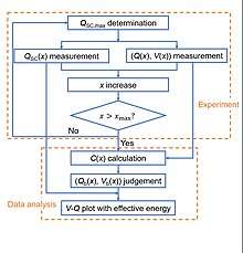
With the breakdown effect considered, a standardized method is proposed for output capability assessment of nanogenerators, which can experimental measure the breakdown limit and Eem of nanogenerators.[49] Former studies on the theoretical model implies that TENG can be considered as a voltage source combining with a capacitor in series, of which the capacitance varies during operation.[52] Based on the capacitive property, the assessment method is developed by charging the target TENG (TENG1) at different displacement x to measure the breakdown condition. Another TENG (TENG2) is added as the high-voltage source to trigger the target TENG to approach the breakdown condition. Switch 1 (S1) and switch 2 (S2) are used to enable different measurement steps. Detailed process flow of this method, including an experiment part and a data analysis part. First of all, it is critical to keep the surface charge density identical as reflected by QSC,max, to ensure the consistency of measurement at different x. Thus in Step 1, S1 was turned on and S2 was turn off to measure QSC,max; if QSC,max is lower than the expected value, additional triboelectrification process is conducted to approach that. And then in Step 2, x was set into a certain value, and the short-circuit charge transfer QSC(x) at a certain x was measured by coulometer Q1. In step 3, S1 was turned off, S2 was turn on, and then the TENG2 was triggered to supply high-voltage output for TENG1. The charge flowing into TENG1 and the voltage across TENG1 was measured at the same time, in which the charge was measured by coulometer Q2, and the voltage was obtained by multiplying the resistance R with the current flowing through it as measured by current meter I, as detailed in Methods. The turning points obtained in this (Q, V) were considered as the breakdown points. And then, if x<xmax, the process was repeated starting from step 1 with an increased x, until xmax was achieved to finish the experimental measurement part. For the data analysis part, first, C(x) was calculated from the slope of the linear part in the measured (Q, V), by considering it as the non-breakdown part. And then, the first turning point (Qb(x), Vb (x)) was determined at the variant R2 value by linearly fitting C(x), which was considered as the threshold breakdown point. Finally, for any x∈[0, xmax], all the (Qb(x), Vb (x)) can be transferred into (QSC(x)- Qb(x), Vb (x)) as the breakdown points plotted in the V-Q cycle to calculate Eem of TENG.
Pyroelectric nanogenerator
A pyroelectric nanogenerator is an energy harvesting device converting the external thermal energy into an electrical energy by using nano-structured pyroelectric materials. Usually, harvesting thermoelectric energy mainly relies on the Seebeck effect that utilizes a temperature difference between two ends of the device for driving the diffusion of charge carriers.[53] However, in an environment that the temperature is spatially uniform without a gradient, such as in the outdoors, the Seebeck effect cannot be used to harvest thermal energy from a time-dependent temperature fluctuation. In this case, the pyroelectric effect has to be the choice, which is about the spontaneous polarization in certain anisotropic solids as a result of temperature fluctuation.[54] The first pyroelectric nanogenerator was introduced by Prof. Zhong Lin Wang at Georgia Institute of Technology in 2012.[55] By harvesting the waste heat energy, this new type of nanogenerator has the potential applications such as wireless sensors, temperature imaging, medical diagnostics, and personal electronics.
Mechanism
The working principle of pyroelectric nanogenerator will be explained for 2 different cases: the primary pyroelectric effect and the secondary pyroelectric effect.
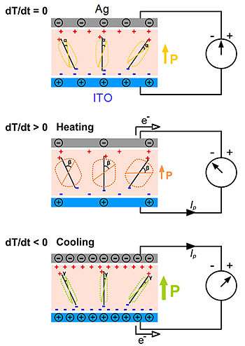
The working principle for the first case is explained by the primary pyroelectric effect, which describes the charge produced in a strain-free case. The primary pyroelectric effect dominates the pyroelectric response in PZT, BTO, and some other ferroelectric materials.[56] The mechanism is based on the thermally induced random wobbling of the electric dipole around its equilibrium axis, the magnitude of which increases with increasing temperature.[57] Due to thermal fluctuations under room temperature, the electric dipoles will randomly oscillate within a degree from their respective aligning axes. Under a fixed temperature, the total average strength of the spontaneous polarization form the electric dipoles is constant, resulting in no output of the pyroelectric nanogenerator. If we apply a change in temperature in the nanogenerator from room temperature to a higher temperature, the increase in temperature will result in that the electric dipoles oscillate within a larger degree of spread around their respective aligning axes. The total average spontaneous polarization is decreased due to the spread of the oscillation angles. The quantity of induced charges in the electrodes are thus reduced, resulting in a flow of electrons. If the nanogenerator is cooled instead of heated, the spontaneous polarization will be enhanced since the electric dipoles oscillate within a smaller degree of spread angles due to the lower thermal activity. The total magnitude of the polarization is increased and the amount of induced charges in the electrodes are increased. The electrons will then flow in an opposite direction.
For the second case, the obtained pyroelectric response is explained by the secondary pyroelectric effect, which describes the charge produced by the strain induced by thermal expansion. The secondary pyroelectric effect dominates the pyroelectric response in ZnO, CdS, and some other wurzite-type materials. The thermal deformation can induce a piezoelectric potential difference across the material, which can drive the electrons to flow in the external circuit. The output of the nanogenerator is associated with the piezoelectric coefficient and the thermal deformation of the materials. The output current I of the pyroelectric nanogenerators can be determined by the equation of I=pA(dT/dt), where p is the pyroelectric coefficient, A is the effective area of the NG, dT/dt is the rate of change in temperature.
Applications
Pyroelectric nanogenerator is expected to be applied for various applications where the time-dependent temperature fluctuation exists. One of the feasible applications of the pyroelectric nanogenerator is used as an active sensor, which can work without a battery. One example has been introduced by Professor Zhong Lin Wang's group in 2012 by using a pyroelectric nanogenerator as the self-powered temperature sensor for detecting a change in temperature, where the response time and reset time of the sensor are about 0.9 and 3 s, respectively.[58] In general, the pyroelectric nanogenerator gives a high output voltage, but the output current is small. It not only can be used as a potential power source, but also as an active sensor for measuring temperature variation.
See also
- Battery (electricity)
- Electrical generator
- Microelectromechanical Systems
- Micropower
- Nanoelectromechanical systems
- Smartdust
- Smart Wearable Systems
References
- Wang, Zhong Lin (November 2019). "On the first principle theory of nanogenerators from Maxwell's equations". Nano Energy. 68: 104272. doi:10.1016/j.nanoen.2019.104272.
- Maxwell, J.C. (1861). Philosophical Magazine and Journal of Science. London: Edinburg and Dubline, Fourth series. p. 161.
- Wang, Zhong Lin; Jiang, Tao; Xu, Liang (September 2017). "Toward the blue energy dream by triboelectric nanogenerator networks". Nano Energy. 39: 9–23. doi:10.1016/j.nanoen.2017.06.035.
- Wang, Zhong Lin (March 2017). "On Maxwell's displacement current for energy and sensors: the origin of nanogenerators". Materials Today. 20 (2): 74–82. doi:10.1016/j.mattod.2016.12.001.
- Wang, Z. L.; Song, J. (June 2006). "Piezoelectric Nanogenerators Based on Zinc Oxide Nanowire Arrays" (PDF). Science. 312 (5771): 242–246. Bibcode:2006Sci...312..242W. doi:10.1126/science.1124005. PMID 16614215.
- Wang, Zhong Lin; Wang, Xudong; Song, Jinhui; Liu, Jin; Gao, Yifan (2008). "Piezoelectric Nanogenerators for Self-Powered Nanodevices" (PDF). IEEE Pervasive Computing. 7 (1): 49–55. doi:10.1109/mprv.2008.14. hdl:1853/25449. Retrieved 2012-06-15.
- Wang, Xudong; Song, Jinhui; Liu, Jin; Wang, Zhong Lin (2007). "Direct-Current Nanogenerator Driven by Ultrasonic Waves" (PDF). Science. 316 (5821): 102–105. Bibcode:2007Sci...316..102W. doi:10.1126/science.1139366. PMID 17412957.
- Choi, M. Y.; Choi, D.; Jin, M. J.; Kim, I.; Kim, S. H.; Choi, J. Y.; Lee, S. Y.; Kim, J. M.; Kim, S. W. (5 June 2009). "Mechanically Powered Transparent Flexible Charge-Generating Nanodevices with Piezoelectric ZnO Nanorods" (PDF). Advanced Materials. 21 (21): 2185–2189. doi:10.1002/adma.200803605. Archived from the original (PDF) on 4 March 2016.
- Choi, D.; Choi, M. Y.; Shin, H. J.; Yoon, S. M.; Seo, J. S.; Choi, J. Y.; Lee, S. Y.; Kim, J. M.; Kim, S. W. (2010). "Nanoscale Networked Single-Walled Carbon-Nanotube Electrodes for Transparent Flexible Nanogenerators" (PDF). Journal of Physical Chemistry C. 114 (2): 1379–1384. doi:10.1021/jp909713c.
- Xu, Sheng; Qin, Yong; Xu, Chen; Wei, Yaguang; Yang, Rusen; Wang, Zhong Lin (2010). "Self-powered nanowire devices" (PDF). Nature Nanotechnology. 5 (5): 366–373. Bibcode:2010NatNa...5..366X. doi:10.1038/nnano.2010.46. PMID 20348913.
- Momeni, K.; Odegard, G. M.; Yassar, R. S. (2010). "Nanocomposite electrical generator based on piezoelectric zinc oxide nanowires" (PDF). Journal of Applied Physics. 108 (11): 114303–114303–7. Bibcode:2010JAP...108k4303M. doi:10.1063/1.3517095.
- Qin, Yong; Wang, Xudong; Wang, Zhong Lin (14 February 2008). "Microfibre–nanowire hybrid structure for energy scavenging" (PDF). Nature. 451 (7180): 809–813. Bibcode:2008Natur.451..809Q. doi:10.1038/nature06601. PMID 18273015.
- corrected in Qin, Yong; Wang, Xudong; Wang, Zhong Lin (15 January 2009). "Microfibre–nanowire hybrid structure for energy scavenging". Nature. 457 (7227): 340. Bibcode:2009Natur.457..340Q. doi:10.1038/nature07628.
- Lin, Y.-F.; Song, J.; Ding, Y.; Lu, S.-Y.; Wang, Z. L. (14 January 2008). "Piezoelectric nanogenerator using CdS nanowires" (PDF). Applied Physics Letters. 92 (2): 022105. Bibcode:2008ApPhL..92b2105L. doi:10.1063/1.2831901.
- Huang, Chi-Te; Song, Jinhui; Lee, Wei-Fan; Ding, Yong; Gao, Zhiyuan; Hao, Yue; Chen, Lih-Juann; Wang, Zhong Lin (7 April 2010). "GaN Nanowire Arrays for High-Output Nanogenerators" (PDF). Journal of the American Chemical Society. 132 (13): 4766–4771. doi:10.1021/ja909863a. PMID 20218713.
- Lu, M. P.; Song, J.; Lu, M. Y.; Chen, M. T.; Gao, Y.; Chen, L. J.; Wang, Z. L. (March 2009). "Piezoelectric Nanogenerator Using p-Type ZnO Nanowire Arrays" (PDF). Nano Letters. 9 (3): 1223–1227. Bibcode:2009NanoL...9.1223L. doi:10.1021/nl900115y. PMID 19209870.
- Wang, Z.; Hu, J.; Suryavanshi, A. P.; Yum, K.; Yu, M. F. (October 2007). "Voltage Generation from Individual BaTiO3 Nanowires under Periodic Tensile Mechanical Load" (PDF). Nano Letters. 7 (10): 2966–2969. Bibcode:2007NanoL...7.2966W. doi:10.1021/nl070814e. PMID 17894515. Archived from the original (PDF) on 2012-12-19.
- Chang, Chieh; Tran, Van H.; Wang, Junbo; Fuh, Yiin-Kuen; Lin, Liwei (10 February 2010). "Direct-Write Piezoelectric Polymeric Nanogenerator with High Energy Conversion Efficiency". Nano Letters. 10 (2): 726–731. Bibcode:2010NanoL..10..726C. doi:10.1021/nl9040719. PMID 20099876.
- Ganeshkumar, Rajasekaran; Sopiha, Kostiantyn V; Wu, Ping; Cheah, Chin Wei; Zhao, Rong (2016-08-30). "Ferroelectric KNbO3nanofibers: synthesis, characterization and their application as a humidity nanosensor". Nanotechnology. 27 (39): 395607. doi:10.1088/0957-4484/27/39/395607. ISSN 0957-4484. PMID 27573538.
- Ganeshkumar, Rajasekaran; Cheah, Chin Wei; Xu, Ruize; Kim, Sang-Gook; Zhao, Rong (2017). "A high output voltage flexible piezoelectric nanogenerator using porous lead-free KNbO3 nanofibers". Applied Physics Letters. 111: 013905. doi:10.1063/1.4992786.
- Xu, Shiyou; Poirier, Gerald; Yao, Nan (2012-05-09). "PMN-PT Nanowires with a Very High Piezoelectric Constant". Nano Letters. 12 (5): 2238–2242. Bibcode:2012NanoL..12.2238X. doi:10.1021/nl204334x. ISSN 1530-6984. PMID 22494473.
- Xu, Shiyou; Yeh, Yao-wen; Poirier, Gerald; McAlpine, Michael C.; Register, Richard A.; Yao, Nan (2013-06-12). "Flexible Piezoelectric PMN–PT Nanowire-Based Nanocomposite and Device". Nano Letters. 13 (6): 2393–2398. Bibcode:2013NanoL..13.2393X. doi:10.1021/nl400169t. ISSN 1530-6984. PMID 23634729.
- Wu, Fan; Cai, Wei; Yeh, Yao-Wen; Xu, Shiyou; Yao, Nan (2016-03-01). "Energy scavenging based on a single-crystal PMN-PT nanobelt". Scientific Reports. 6: 22513. Bibcode:2016NatSR...622513W. doi:10.1038/srep22513. ISSN 2045-2322. PMC 4772540. PMID 26928788.
- Xu, Chen; Wang, Xudong; Wang, Zhong Lin (29 April 2009). "Nanowire Structured Hybrid Cell for Concurrently Scavenging Solar and Mechanical Energies" (PDF). Journal of the American Chemical Society. 131 (16): 5866–5872. doi:10.1021/ja810158x. PMID 19338339. Archived from the original (PDF) on 3 March 2016.
- Hansen, Benjamin J.; Liu, Ying; Yang, Rusen; Wang, Zhong Lin (27 July 2010). "Hybrid Nanogenerator for Concurrently Harvesting Biomechanical and Biochemical Energy" (PDF). ACS Nano. 4 (7): 3647–3652. CiteSeerX 10.1.1.600.6928. doi:10.1021/nn100845b. PMID 20507155.
- Yang, R.; Qin, Y.; Li, C.; Zhu, G.; Wang, Z. L. (March 2009). "Converting Biomechanical Energy into Electricity by a Muscle-Movement-Driven Nanogenerator" (PDF). Nano Letters. 9 (3): 1201–1205. Bibcode:2009NanoL...9.1201Y. doi:10.1021/nl803904b. PMID 19203203.
- Choi, Dukhyun; Choi, Min-Yeol; Choi, Won Mook; Shin, Hyeon-Jin; Park, Hyun-Kyu; Seo, Ju-Seok; Park, Jongbong; Yoon, Seon-Mi; Chae, Seung Jin; Lee, Young Hee; Kim, Sang-Woo; Choi, Jae-Young; Lee, Sang Yoon; Kim, Jong Min (18 May 2010). "Fully Rollable Transparent Nanogenerators Based on Graphene Electrodes". Advanced Materials. 22 (19): 2187–2192. doi:10.1002/adma.200903815. PMID 20376853.
- Fan, F. R.; Tian, Z. Q.; Lin Wang, Z. (2012). "Flexible triboelectric generator". Nano Energy. 1 (2): 328–334. doi:10.1016/j.nanoen.2012.01.004.
- Wang, Z. L. (2013). "Triboelectric Nanogenerators as New Energy Technology for Self-Powered Systems and as Active Mechanical and Chemical Sensors". ACS Nano. 7 (11): 9533–9557. doi:10.1021/nn404614z. PMID 24079963.
- Xiong, Pu (25 September 2015). "Efficient Charging of Li-Ion Batteries with Pulsed Output Current of Triboelectric Nanogenerators". Advanced Science. 3 (1): 1500255. doi:10.1002/advs.201500255. PMC 5054865. PMID 27774382.
- Pacha, Aswathi (2017-12-30). "Nanogenerators go wireless". The Hindu. ISSN 0971-751X. Retrieved 2019-08-15.
- Mallineni, Sai Sunil Kumar; Dong, Yongchang; Behlow, Herbert; Rao, Apparao M.; Podila, Ramakrishna (2018). "A Wireless Triboelectric Nanogenerator". Advanced Energy Materials. 8 (10): 1702736. arXiv:1707.03677. doi:10.1002/aenm.201702736. ISSN 1614-6840.
- Zhu, G.; Pan, C.; Guo, W.; Chen, C. Y.; Zhou, Y.; Yu, R.; Wang, Z. L. (2012). "Triboelectric-Generator-Driven Pulse Electrodeposition for Micropatterning". Nano Letters. 12 (9): 4960–4965. Bibcode:2012NanoL..12.4960Z. doi:10.1021/nl302560k. PMID 22889363.
- Wang, S.; Lin, L.; Wang, Z. L. (2012). "Nanoscale Triboelectric-Effect-Enabled Energy Conversion for Sustainably Powering Portable Electronics". Nano Letters. 12 (12): 6339–6346. Bibcode:2012NanoL..12.6339W. CiteSeerX 10.1.1.653.8167. doi:10.1021/nl303573d. PMID 23130843.
- Wang, S.; Lin, L.; Xie, Y.; Jing, Q.; Niu, S.; Wang, Z. L. (2013). "Sliding-Triboelectric Nanogenerators Based on In-Plane Charge-Separation Mechanism". Nano Letters. 13 (5): 2226–2233. Bibcode:2013NanoL..13.2226W. CiteSeerX 10.1.1.653.7572. doi:10.1021/nl400738p. PMID 23581714.
- Zhu, G.; Chen, J.; Liu, Y.; Bai, P.; Zhou, Y. S.; Jing, Q.; Pan, C.; Wang, Z. L. (2013). "Linear-Grating Triboelectric Generator Based on Sliding Electrification". Nano Letters. 13 (5): 2282–2289. Bibcode:2013NanoL..13.2282Z. doi:10.1021/nl4008985. PMID 23577639.
- Lin, L.; Wang, S.; Xie, Y.; Jing, Q.; Niu, S.; Hu, Y.; Wang, Z. L. (2013). "Segmentally Structured Disk Triboelectric Nanogenerator for Harvesting Rotational Mechanical Energy". Nano Letters. 13 (6): 2916–2923. Bibcode:2013NanoL..13.2916L. CiteSeerX 10.1.1.653.6174. doi:10.1021/nl4013002. PMID 23656350.
- Yang, Y.; Zhou, Y. S.; Zhang, H.; Liu, Y.; Lee, S.; Wang, Z. L. (2013). "A Single-Electrode Based Triboelectric Nanogenerator as Self-Powered Tracking System". Advanced Materials. 25 (45): 6594–6601. doi:10.1002/adma.201302453. PMID 24166972.
- Yang, Y.; Zhang, H.; Chen, J.; Jing, Q.; Zhou, Y. S.; Wen, X.; Wang, Z. L. (2013). "Single-Electrode-Based Sliding Triboelectric Nanogenerator for Self-Powered Displacement Vector Sensor System". ACS Nano. 7 (8): 7342–7351. doi:10.1021/nn403021m. PMID 23883397.
- Yang, W.; Chen, J.; Zhu, G.; Wen, X.; Bai, P.; Su, Y.; Lin, Y.; Wang, Z. (2013). "Harvesting vibration energy by a triple-cantilever based triboelectric nanogenerator". Nano Research. 6 (12): 880–886. doi:10.1007/s12274-013-0364-0.
- Yang, W.; Chen, J.; Zhu, G.; Yang, J.; Bai, P.; Su, Y.; Jing, Q.; Cao, X.; Wang, Z. L. (2013). "Harvesting Energy from the Natural Vibration of Human Walking". ACS Nano. 7 (12): 11317–11324. doi:10.1021/nn405175z. PMID 24180642.
- Chen, J.; Zhu, G.; Yang, W.; Jing, Q.; Bai, P.; Yang, Y.; Hou, T. C.; Wang, Z. L. (2013). "Harmonic-Resonator-Based Triboelectric Nanogenerator as a Sustainable Power Source and a Self-Powered Active Vibration Sensor". Advanced Materials. 25 (42): 6094–6099. doi:10.1002/adma.201302397. PMID 23999798.
- Sala de Medeiros, Marina; Chanci, Daniela; Moreno, Carolina; Goswami, Debkalpa; Martinez, Ramses V. (2019-07-25). "Waterproof, Breathable, and Antibacterial Self‐Powered e‐Textiles Based on Omniphobic Triboelectric Nanogenerators". Advanced Functional Materials. 29 (42): 1904350. doi:10.1002/adfm.201904350. ISSN 1616-301X.
- Fan, F. R.; Lin, L.; Zhu, G.; Wu, W.; Zhang, R.; Wang, Z. L. (2012). "Transparent Triboelectric Nanogenerators and Self-Powered Pressure Sensors Based on Micropatterned Plastic Films". Nano Letters. 12 (6): 3109–3114. Bibcode:2012NanoL..12.3109F. CiteSeerX 10.1.1.454.4211. doi:10.1021/nl300988z. PMID 22577731.
- Taghavi, Majid; Mattoli, Virgilio; Sadeghi, Ali; Mazzolai, Barbara; Beccai, Lucia (1400024). "A Novel Soft Metal-Polymer Composite for Multidirectional Pressure Energy Harvesting". Advanced Energy Materials. 4 (12): 1400024. doi:10.1002/aenm.201400024. Check date values in:
|date=(help) - Lin, L.; Xie, Y.; Wang, S.; Wu, W.; Niu, S.; Wen, X.; Wang, Z. L. (2013). "Triboelectric Active Sensor Array for Self-Powered Static and Dynamic Pressure Detection and Tactile Imaging". ACS Nano. 7 (9): 8266–8274. doi:10.1021/nn4037514. PMID 23957827.
- Taghavi, Majid; Sedeghi, Ali; Mondini, Alessio; Mazzolai, Barbara; Beccai, Lucia; Mattoli, Virgilio (2015). "Triboelectric smart machine elements and self-powered encoder". Nano Energy. 13: 92–102. doi:10.1016/j.nanoen.2015.02.011.
- Lin, Z. H.; Zhu, G.; Zhou, Y. S.; Yang, Y.; Bai, P.; Chen, J.; Wang, Z. L. (2013). "A Self-Powered Triboelectric Nanosensor for Mercury Ion Detection". Angewandte Chemie. 125 (19): 5169–5173. doi:10.1002/ange.201300437.
- Zi, Yunlong; Niu, Simiao; Wang, Jie; Wen, Zhen; Tang, Wei; Wang, Zhong Lin (2015). "Standards and Figure-of-Merits for Quantifying the Performance of Triboelectric Nanogenerators". Nature Communications. 6:8376: 8376. doi:10.1038/ncomms9376. PMC 4598564. PMID 26406279.
- Xia, Xin; Fu, Jingjing; Zi, Yunlong (2019). "A Universal Standardized Method for Output Capability Assessment of Nanogenerators". Nature Communications. 10:4428 (1): 4428. doi:10.1038/s41467-019-12465-2. PMC 6765008. PMID 31562336.
- Zi, Yunlong; Wu, Changsheng; Ding, Wenbo; Wang, Zhong Lin (2017). "Maximized Effective Energy Output of Contact-Separation-Triggered Triboelectric Nanogenerators as Limited by Air Breakdown". Advanced Functional Materials. 27 (24): 1700049. doi:10.1002/adfm.201700049.
- Xu, Guoqiang; Li, Xiaoyi; Xia, Xin; Fu, Jingjing; Ding, Wenbo; Zi, Yunlong (2019). "On the force and energy conversion in triboelectric nanogenerators". Nano Energy. 59: 154–161. doi:10.1016/j.nanoen.2019.02.035.
- Niu, Simiao; Wang, Zhong Lin (2015). "Theoretical systems of triboelectric nanogenerators". Nano Energy. 14: 161–191. doi:10.1016/j.nanoen.2014.11.034.
- Yang, Y.; Pradel, K. C.; Jing, Q.; Wu, J. M.; Zhang, F.; Zhou, Y.; Zhang, Y.; Wang, Z. L. (2012). "Thermoelectric Nanogenerators Based on Single Sb-Doped ZnO Micro/Nanobelts". ACS Nano. 6 (8): 6984–6989. doi:10.1021/nn302481p. PMID 22742540.
- Zook, J. D.; Liu, S. T. (1978). "Pyroelectric effects in thin film". Journal of Applied Physics. 49 (8): 4604. Bibcode:1978JAP....49.4604Z. doi:10.1063/1.325442.
- Yang, Y.; Guo, W.; Pradel, K. C.; Zhu, G.; Zhou, Y.; Zhang, Y.; Hu, Y.; Lin, L.; Wang, Z. L. (2012). "Pyroelectric Nanogenerators for Harvesting Thermoelectric Energy". Nano Letters. 12 (6): 2833–2838. Bibcode:2012NanoL..12.2833Y. CiteSeerX 10.1.1.654.3691. doi:10.1021/nl3003039. PMID 22545631.
- Ye, C. P.; Tamagawa, T.; Polla, D. L. (1991). "Experimental studies on primary and secondary pyroelectric effects in Pb(ZrOxTi1−x)O3, PbTiO3, and ZnO thin films". Journal of Applied Physics. 70 (10): 5538. Bibcode:1991JAP....70.5538Y. doi:10.1063/1.350212.
- Yang, Y.; Jung, J. H.; Yun, B. K.; Zhang, F.; Pradel, K. C.; Guo, W.; Wang, Z. L. (2012). "Flexible Pyroelectric Nanogenerators using a Composite Structure of Lead-Free KNbO3 Nanowires". Advanced Materials. 24 (39): 5357–5362. doi:10.1002/adma.201201414. PMID 22837044.
- Yang, Y.; Zhou, Y.; Wu, J. M.; Wang, Z. L. (2012). "Single Micro/Nanowire Pyroelectric Nanogenerators as Self-Powered Temperature Sensors". ACS Nano. 6 (9): 8456–8461. doi:10.1021/nn303414u. PMID 22900676.
External links
- Professor Z. L. Wang's Nano Research Group at Georgia Institute of Technology
- Nano Electronic Science & Engineering Laboratory (NESEL) at Sungkyunkwan University (SKKU)
- Laboratory for Nanoscale Mechanics and Physics at University of Illinois, Urbana-Champaign
- LINLAB at University of California, Berkeley
- Samsung Advanced Institute of Technology