MRI artifact
An MRI artifact is a visual artifact (an anomaly seen during visual representation) in magnetic resonance imaging (MRI). It is a feature appearing in an image that is not present in the original object.[1] Many different artifacts can occur during MRI, some affecting the diagnostic quality, while others may be confused with pathology. Artifacts can be classified as patient-related, signal processing-dependent and hardware (machine)-related.[1]
Patient-related MR artifacts
Motion artifacts
A motion artifact is one of the most common artifacts in MR imaging.[2] Motion can cause either ghost images or diffuse image noise in the phase-encoding direction. The reason for mainly affecting data sampling in the phase-encoding direction is the significant difference in the time of acquisition in the frequency- and phase-encoding directions.[1]
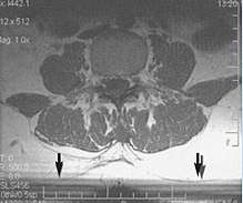
Frequency-encoding sampling in all the rows of the matrix (128, 256 or 512) takes place during a single echo (milliseconds). Phase-encoded sampling takes several seconds, or even minutes, owing to the collection of all the k-space lines to enable Fourier analysis. Major physiological movements are of millisecond to seconds duration and thus too slow to affect frequency-encoded sampling, but they have a pronounced effect in the phase-encoding direction. Periodic movements such as cardiac movement and blood vessel or CSF pulsation cause ghost images, while non-periodic movement causes diffuse image noise (Fig. 1). Ghost image intensity increases with amplitude of movement and the signal intensity from the moving tissue. Several methods can be used to reduce motion artifacts, including patient immobilisation, cardiac and respiratory gating, signal suppression of the tissue causing the artifact, choosing the shorter dimension of the matrix as the phase-encoding direction, view-ordering or phase-reordering methods and swapping phase and frequency-encoding directions to move the artifact out of the field of interest.[1]
Flow
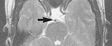
Flow can manifest as either an altered intravascular signal (flow enhancement or flow-related signal loss), or as flow-related artifacts (ghost images or spatial misregistration). Flow enhancement, also known as inflow effect, is caused by fully magnetised protons entering the imaged slice while the stationary protons have not fully regained their magnetization.[1]
The fully magnetized protons yield a high signal in comparison with the rest of the surroundings. High velocity flow causes the protons entering the image to be removed from it by the time the 180-degree pulse is administered. The effect is that these protons do not contribute to the echo and are registered as a signal void or flow-related signal loss (Fig. 2).[1]
Spatial misregistration manifests as displacement of an intravascular signal owing to position encoding of a voxel in the phase direction preceding frequency encoding by time TE/2.The intensity of the artifact is dependent on the signal intensity from the vessel, and is less apparent with increased TE.[1]
Metal artifacts

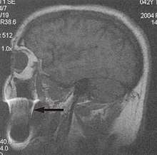
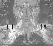
Metal artifacts occur at interfaces of tissues with different magnetic susceptibilities, which cause local magnetic fields to distort the external magnetic field. This distortion changes the precession frequency in the tissue leading to spatial mismapping of information. The degree of distortion depends on the type of metal (stainless steel having a greater distorting effect than titanium alloy), the type of interface (most striking effect at soft tissue-metal interfaces), pulse sequence and imaging parameters. Metal artifacts are caused by external ferromagnetics such as cobalt containing make-up, internal ferromagnetics such as surgical clips, spinal hardware and other orthopaedic devices, and in some cases, metallic objects swallowed by people with pica.[3] Manifestation of these artifacts is variable, including total signal loss, peripheral high signal and image distortion (Figs 3 and 4).[1]
Reduction of these artifacts can be attempted by orientating the long axis of an implant or device parallel to the long axis of the external magnetic field, possible with mobile extremity imaging and an open magnet. Further methods used are choosing the appropriate frequency encoding direction, since metal artifacts are most pronounced in this direction, using smaller voxel sizes, fast imaging sequences, increased readout bandwidth and avoiding gradient-echo imaging when metal is present. A technique called MARS (metal artifact reduction sequence) applies an additional gradient, along the slice select gradient at the time the frequency encoding gradient is applied.
Signal processing dependent artifacts
The ways in which the data are sampled, processed and mapped out on the image matrix manifest these artifacts.[1]
Chemical shift artifact

Chemical shift artifact occurs at the fat/water interface in the phase encoding or section-select directions (Fig. 5). These artifacts arise due to the difference in resonance of protons as a result of their micromagnetic environment. The protons of fat resonate at a slightly lower frequency than those of water. High field strength magnets are particularly susceptible to this artifact.[1]
Determination of the artifact can be made by swapping the phase- and frequency-encoding gradients and examining the resultant shift (if any) of the tissues.
Partial volume
Partial volume artifacts arise from the size of the voxel over which the signal is averaged. Objects smaller than the voxel dimensions lose their identity, and loss of detail and spatial resolution occurs. Reduction of these artifacts is accomplished by using a smaller pixel size and/or a smaller slice thickness.[1]
Wrap-around


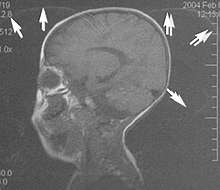
A wrap-around artifact also known as an aliasing artifact, is a result of mismapping of anatomy that lies outside the field of view but within the slice volume.[4] The selected field of view is smaller than the size of the imaged object. The anatomy is usually displaced to the opposite side of the image (Figs 6 and 7). It can be caused by non-linear gradients or by undersampling of the frequencies contained within the return signal.[1]
The sampling rate must be twice the maximal frequency that occurs in the object (Nyquist sampling limit). If not, the Fourier transform will assign very low values to the frequency signals greater than the Nyquist limit. These frequencies will then ‘wrap around’ to the opposite side of the image, masquerading as low-frequency signals. In the frequency encode direction a filter can be applied to the acquired signal to eliminate frequencies greater than the Nyquist frequency. In the phase encode direction, artifacts can be reduced by an increasing number of phase encode steps (increased image time). For correction, a larger field of view may be chosen.[1]
Gibbs artifacts
Gibbs artifacts or Gibbs ringing artifacts, also known as truncation artifacts are caused by the under-sampling of high spatial frequencies at sharp boundaries in the image.[5][6]
Lack of appropriate high-frequency components leads to an oscillation at a sharp transition known as a ringing artifact. It appears as multiple, regularly spaced parallel bands of alternating bright and dark signal that slowly fade with distance (Fig. 8). Ringing artifacts are more prominent in smaller digital matrix sizes.[1]
Methods employed to correct Gibbs artifact include filtering the k-space data prior to Fourier transform, increasing the matrix size for a given field of view, the Gegenbauer reconstruction and Bayesian approach.[1]
Machine/hardware-related artifacts
This is a wide and still expanding subject. Only a few common artifacts are recognised. [1]
Radiofrequency (RF) quadrature
RF detection circuit failure arises from improper detector channel operation. Fourier-transformed data display a bright spot in the centre of the image. If one channel of the detector has a higher gain than the other it will result in object ghosting in the image. This is the result of a hardware failure and must be addressed by a service representative.[1]
External magnetic field (B0) inhomogeneity

B0 inhomogeneity leads to mismapping of tissues. Inhomogeneous external magnetic field causes either spatial, intensity, or both distortions. Intensity distortion occurs when the field in a location is greater or less than in the rest of the imaged object (Fig. 9). Spatial distortion results from long-range field gradients, which remain constant in the inhomogeneous field.[1]
Gradient field artifacts (B1 inhomogeneity)
Magnetic field gradients are used to spatially encode the location of signals from excited protons within the volume being imaged. The slice select gradient defines the volume (slice). Phase- and frequency-encoding gradients provide the information in the other two dimensions. Any deviation in the gradient would be represented as a distortion.[1]
As the distance increases from the centre of the applied gradient, loss of field strength occurs at the periphery. Anatomical compression occurs and is especially pronounced on coronal and sagittal imaging.[1]
When the phase-encoding gradient is different, the width or height of the voxel is different, resulting in distortion. Anatomical proportions are compressed along one or the other axis. Square pixels (and voxels) should be obtained.[1]
Ideally the phase gradient should be assigned to the smaller dimension of the object and the frequency gradient to the larger dimension. In practice this is not always possible because of the necessity of displacing motion artifacts.[1]
This may be corrected by reducing the field of view, by lowering the gradient field strength or by decreasing the frequency bandwidth of radio signal. If correction is not achieved, the cause might be either a damaged gradient coil or an abnormal current passing through the gradient coil.[1]
RF inhomogeneity
Variation in intensity across the image may be due to the failure of the RF coil, non-uniform B1 field, non-uniform sensitivity of the receive only coil (spaces between wire in the coil, uneven distribution of wire), or presence of non-ferromagnetic material in the imaged object.[1]
Asymmetrical brightness
There is a uniform decrease in signal intensity along the frequency encoding axis. Signal drop-off is due to filters that are too tight about the signal band. Some of the signal generated by the imaged section is, thereby, inappropriately rejected. A similar artifact may be caused by non-uniformity in slice thickness.[1]
RF noise
RF pulses and precessional frequencies of MRI instruments occupy the same frequency bandwidth as common sources such as TV, radio, fluorescent lights and computers. Stray RF signals can cause various artifacts. Narrow-band noise is projected perpendicular to the frequency- encoding direction. Broadband noise disrupts the image over a much larger area. Appropriate site planning, proper installation and RF shielding (Faraday cage) eliminate stray RF interference.[1]
Zero line and star artifacts
A bright linear signal in a dashed pattern that decreases in intensity across the screen and can occur as a line or star pattern, depending on the position of the patient in the ‘phase-frequency space’.[1]
Zero line and star artifacts are due to system noise or any cause of RF pollution within the room (Faraday cage). If this pattern persists, check for sources of system noise such as bad electronics or alternating current line noise, loose connections to surface coils, or any source of RF pollution. If a star pattern is encountered, the manufacturer needs to readjust the system software so that the image is moved off the zero point.[1]
Zipper artifacts
Although less common, zippers are bands through the image centre due to an imperfect Faraday cage, with RF pollution in, but originating from outside, the cage.[7] Residual free induction decay stimulated echo also causes zippers.[1]
RF tip angle inhomogeneity
These are patchy areas of increased or decreased signal intensity. This artifact is produced by variations in RF energy required to tip protons 90 or 180 degrees within the selected slice volume.[1]
Bounce point artifact

Absence of signal from tissues of a particular T1 value is a consequence of magnitude sensitive reconstruction in inversion recovery imaging. When the chosen T1 equals 69% of the T1 value of a particular tissue, a bounce point artifact occurs.[1]
Use phase-sensitive reconstruction inversion recovery techniques.
Surface coil artifacts
Close to the surface coil the signals are very strong resulting in a very intense image signal (Fig. 10).[1]
Further from the coil the signal strength drops rapidly due to the attenuation with a loss of image brightness and significant shading to the uniformity. Surface coil sensitivity intensifies problems related to RF attenuation and RF mismatching.
Slice-to-slice interference
Non-uniform RF energy received by adjacent slices during a multi-slice acquisition is due to cross-excitation of adjacent slices with contrast loss in reconstructed images (Fig. 11). To overcome these interference artifacts, the acquisition of two independent sets of gapped multi-slice images need to be included, and subsequently reordered during display of the full image set.[1]
References
- Erasmus, L.J.; Hurter, D.; Naude, M.; Kritzinger, H.G.; Acho, S. (2004). "A short overview of MRI artifacts". South African Journal of Radiology. 8 (2). doi:10.4102/sajr.v8i2.127. ISSN 2078-6778. (CC-BY 4.0)
- Zaitsev, M; Maclaren, J; Herbst, M (October 2015). "Motion artifacts in MRI: A complex problem with many partial solutions". Journal of Magnetic Resonance Imaging. 42 (4): 887–901. doi:10.1002/jmri.24850. PMC 4517972. PMID 25630632.
- "Doctors pull out 38 metal objects including keys, coins, a SIM card, pencil sharpener blade and a magnet 'they were stuck to' from inside man's stomach | NEWS.am Medicine - All about health and medicine". med.news.am. Retrieved 2019-03-16.
- Yeung, J. "Aliasing in MRI | Radiology Reference Article | Radiopaedia.org". Radiopaedia. Retrieved 26 May 2019.
- Bashir, Usman. "Gibbs and truncation artifacts | Radiology Reference Article | Radiopaedia.org". Radiopaedia. Retrieved 26 May 2019.
- Ferreira, P. F.; Gatehouse, P. D.; Mohiaddin, R. H.; Firmin, D. N. (2013). "Cardiovascular magnetic resonance artefacts". Journal of Cardiovascular Magnetic Resonance. 15: 20. doi:10.1186/1532-429X-15-41. PMC 3674921. PMID 23697969.
- Bashir, Usman. "Zipper artifact | Radiology Reference Article | Radiopaedia.org". Radiopaedia. Retrieved 26 May 2019.