Hitachi HD44780 LCD controller
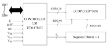
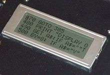
The Hitachi HD44780 LCD controller is an alphanumeric dot matrix liquid crystal display (LCD) controller developed by Hitachi. The character set of the controller includes ASCII characters, Japanese Kana characters, and some symbols in two 28 character lines. Using an extension driver, the device can display up to 80 characters.[1] The HD44780 is one of the most popular character LCDs ever made, with numerous third-party displays utilizing its 16-pin interface and instruction set for compatibility.
Architecture
The Hitachi HD44780 LCD controller is limited to monochrome text displays and is often used in copiers, fax machines, laser printers, industrial test equipment, networking equipment, such as routers and storage devices.
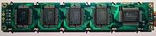
Compatible LCD screens are manufactured in several standard configurations. Common sizes are one row of eight characters (8x1), and 16×2, 20×2 and 20×4 formats. Larger custom sizes are made with 32, 40 and 80 characters and with 1, 2, 4 or 8 lines. The most commonly manufactured larger configuration is 40x4 characters, which requires two individually addressable HD44780 controllers with expansion chips as a single HD44780 chip can only address up to 80 characters.
Character LCDs may have a backlight, which may be LED, fluorescent, or electroluminescent.
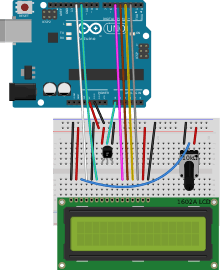
Character LCDs use a 16 contact interface, commonly using pins or card edge connections on 0.1 inch (2.54 mm) centers. Those without backlights may have only 14 pins, omitting the two pins powering the light. This interface was designed to be easily hooked up to the Intel MCS-51 XRAM interface, using only two address pins, which allowed displaying text on LCD using simple MOVX commands, offering cost effective option for adding text display to devices. The pinout is as follows:
- Ground
- VCC +3.3 to +5V (typical)
- Contrast adjustment (VO) This is an analog input, typically connected to a potentiometer. The user must be able to control this voltage independent of all other adjustments, in order to optimise visibility of the display that varies i.a. with temperature, and, in some cases height above the sea level. With a wrong adjustment the display will seem to malfunction.
- Register Select (RS). RS=0: Command, RS=1: Data
- Read/Write (R/W). R/W=0: Write, R/W=1: Read (In most applications reading from the HD44780 makes no sense. In that case this pin can be permanently connected to ground and no io pins need to be allocated to steer it.)
- Clock (Enable). Falling edge triggered
- Bit 0 (Not used in 4-bit operation)
- Bit 1 (Not used in 4-bit operation)
- Bit 2 (Not used in 4-bit operation)
- Bit 3 (Not used in 4-bit operation)
- Bit 4
- Bit 5
- Bit 6
- Bit 7
- Backlight Anode (+) (If applicable)
- Backlight Cathode (-) (If applicable)
The nominal operating voltage for LED backlights is 5V at full brightness, with dimming at lower voltages dependent on the details such as LED color. Non-LED backlights often require higher voltages (I.E. electroluminescent).
Mode selection
Selecting 4-bit or 8-bit mode requires careful selection of commands. There are two primary considerations. First, with D3-D0 unconnected, these lines will always appear low (0b0000) to the HD44780 when it is in 8-bit mode. Second, the LCD may initially be in one of three states:
- (State1) 8-bit mode
- (State2) 4-bit mode, waiting for the first set of 4 bits
- (State3) 4-bit mode, waiting for the second set of 4 bits
State3 may occur, for example, if a prior control was aborted after sending only the first 4 bits of a command while the LCD was in 4-bit mode.
The following algorithm ensures that the LCD is in the desired mode:
- Set D7-D4 to 0b0011, and toggle the enable bit.
- If in State1, the LCD will see the command as 0b0011_0000, and thus remain in 8-bit mode (State1).
- If in State2, the LCD will simply latch the value 0b0011 into bits 7-4 and then move to State3.
- If in State3, the LCD will latch the value 0b0011 into bits 3-0, and then execute a random command based on the (unknown to us) values in bits 7-4, after which it will either be in State1 (if the unknown bits happened to be 0b0011), or State2 (if the unknown bits were anything else).
- Repeat the above, setting D7-D4 to 0b0011 and toggling the enable bit again.
- If in State1, the LCD will remain in 8-bit mode (State1) just as above.
- If in State2, it will latch the value into bits 7-4 and move to State3, just as above.
- If in State3, the LCD will latch the value into bits 3-0 just as above and execute a command. However, the command will no longer be random, but will be the 0b0011 that was latched from State2 in the previous iteration. Thus, the LCD will switch to 8-bit mode and change to State1.
- The LCD is now in either State1 or State 3. Repeat the previous step one more time.
- If in State1, the LCD will remain in 8-bit mode (and thus State1).
- The LCD can no longer be in State2 at this point.
- If in State3, the LCD will latch the value into bits 3-0 and execute a command, which will be the 0b0011 that was latched from State2 in the previous iteration, thus switching the LCD to 8-bit mode and State1.
- Now that the LCD is definitely in 8-bit mode, it can be switched to 4-bit mode if desired. To do so, set D7-D4 to 0b0010 and toggle the enable bit. This will leave the LCD in 4-bit mode, configured for a single line and 5x8 fonts.
- Issue any desired additional Function Set commands to specify the number of lines and the font to use, being sure to use the appropriate value for bit 4 so as to remain in the desired mode (0 for 4-bit and 1 for 8-bit).
Once in 4-bit mode, character and control data are transferred as pairs of 4-bit "nibbles" on the upper data pins, D7-D4. The four most significant bits (7-4) must be written first, followed by the four least significant bits (3-0).
Instruction set
The HD44780 instruction set is shown below:[2]
| Instruction | Code | Description | Execution time (max) (when fcp = 270 kHz) | |||||||||
|---|---|---|---|---|---|---|---|---|---|---|---|---|
| RS | R/W | B7 | B6 | B5 | B4 | B3 | B2 | B1 | B0 | |||
| Clear display | 0 | 0 | 0 | 0 | 0 | 0 | 0 | 0 | 0 | 1 | Clears display and returns cursor to the home position (address 0). | 1.52 ms |
| Cursor home | 0 | 0 | 0 | 0 | 0 | 0 | 0 | 0 | 1 | * | Returns cursor to home position. Also returns display being shifted to the original position. DDRAM content remains unchanged. | 1.52 ms |
| Entry mode set | 0 | 0 | 0 | 0 | 0 | 0 | 0 | 1 | I/D | S | Sets cursor move direction (I/D); specifies to shift the display (S). These operations are performed during data read/write. | 37 μs |
| Display on/off control | 0 | 0 | 0 | 0 | 0 | 0 | 1 | D | C | B | Sets on/off of all display (D), cursor on/off (C), and blink of cursor position character (B). | 37 μs |
| Cursor/display shift | 0 | 0 | 0 | 0 | 0 | 1 | S/C | R/L | * | * | Sets cursor-move or display-shift (S/C), shift direction (R/L). DDRAM content remains unchanged. | 37 μs |
| Function set | 0 | 0 | 0 | 0 | 1 | DL | N | F | * | * | Sets interface data length (DL), number of display line (N), and character font (F). | 37 μs |
| Set CGRAM address | 0 | 0 | 0 | 1 | CGRAM address | Sets the CGRAM address. CGRAM data are sent and received after this setting. | 37 μs | |||||
| Set DDRAM address | 0 | 0 | 1 | DDRAM address | Sets the DDRAM address. DDRAM data are sent and received after this setting. | 37 μs | ||||||
| Read busy flag & address counter |
0 | 1 | BF | CGRAM/DDRAM address | Reads busy flag (BF) indicating internal operation being performed and reads CGRAM or DDRAM address counter contents (depending on previous instruction). | 0 μs | ||||||
| Write CGRAM or DDRAM |
1 | 0 | Write Data | Write data to CGRAM or DDRAM. | 37 μs | |||||||
| Read from CG/DDRAM | 1 | 1 | Read Data | Read data from CGRAM or DDRAM. | 37 μs | |||||||
| Instruction bit names — I/D - 0 = decrement cursor position, 1 = increment cursor position; S - 0 = no display shift, 1 = display shift; D - 0 = display off, 1 = display on; C - 0 = cursor off, 1 = cursor on; B - 0 = cursor blink off, 1 = cursor blink on ; S/C - 0 = move cursor, 1 = shift display; R/L - 0 = shift left, 1 = shift right; DL - 0 = 4-bit interface, 1 = 8-bit interface; N - 0 = 1/8 or 1/11 duty (1 line), 1 = 1/16 duty (2 lines); F - 0 = 5×8 dots, 1 = 5×10 dots; BF - 0 = can accept instruction, 1 = internal operation in progress. | ||||||||||||
Font
The original HD44780 character generator ROM contains 208 characters in a 5×8 dot matrix, and 32 characters in a 5×10 dot matrix. More recent compatible chips are available with higher resolution, matched to displays with more pixels.
Two versions of the ROM have been developed:[3]
- HD44780UA00, the standard (Japanese) version, which includes katakana characters and some Greek letters and mathematical symbols
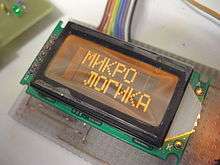
- HD44780UA02, a European version, which includes the complete set of Greek, Cyrillic and Western European characters (with diacritics)
The 7-bit ASCII subset for the Japanese version is non-standard: it supplies a Yen symbol where the backslash character is normally found, and left and right arrow symbols in place of tilde and the rubout character.
A limited number of custom characters can be programmed into the device in the form of a bitmap using special commands. These characters have to be written to the device each time it is switched on, as they are stored in volatile memory.
See also
- LCD Smartie - Open source display driver for Microsoft Windows
References
- Sanchez & Canton 2007, p. 275
- Huang 2009, p. 326
- "HD44780U datasheet" (PDF).
Further reading
- Huang, Han-Way (2009). The HCS12 / 9S12: An Introduction to Software and Hardware Interfacing (2nd ed.). Delmar Cengage Learning. ISBN 978-1-4354-2742-6.
- Sanchez, Julio; Canton, Maria P. (2007). Microcontroller Programming: the Microchip PIC. CRC Press. ISBN 978-0-8493-7189-9.