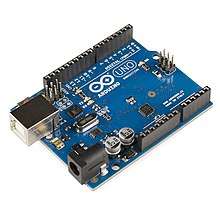
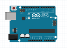
Arduino Uno
The Arduino Uno is an open-source microcontroller board based on the Microchip ATmega328P microcontroller and developed by Arduino.cc.[2][3] The board is equipped with sets of digital and analog input/output (I/O) pins that may be interfaced to various expansion boards (shields) and other circuits.[1] The board has 14 digital I/O pins (six capable of PWM output), 6 analog I/O pins, and is programmable with the Arduino IDE (Integrated Development Environment), via a type B USB cable.[4] It can be powered by the USB cable or by an external 9-volt battery, though it accepts voltages between 7 and 20 volts. It is similar to the Arduino Nano and Leonardo.[5][6] The hardware reference design is distributed under a Creative Commons Attribution Share-Alike 2.5 license and is available on the Arduino website. Layout and production files for some versions of the hardware are also available.
 Arduino Uno SMD R3 | |
| Developer | Arduino |
|---|---|
| Manufacturer | Many |
| Type | Single-board microcontroller[1] |
| Retail availability | https://store.arduino.cc/usa/ |
| Operating system | None |
| CPU | Microchip AVR (8-bit) |
| Memory | SRAM |
| Storage | Flash, EEPROM |
The word "uno" means "one" in Italian and was chosen to mark the initial release of Arduino Software.[1] The Uno board is the first in a series of USB-based Arduino boards;[3] it and version 1.0 of the Arduino IDE were the reference versions of Arduino, which have now evolved to newer releases.[4] The ATmega328 on the board comes preprogrammed with a bootloader that allows uploading new code to it without the use of an external hardware programmer.[3]
While the Uno communicates using the original STK500 protocol,[1] it differs from all preceding boards in that it does not use the FTDI USB-to-serial driver chip. Instead, it uses the Atmega16U2 (Atmega8U2 up to version R2) programmed as a USB-to-serial converter.[7]
History
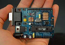
The Arduino project started at the Interaction Design Institute Ivrea (IDII) in Ivrea, Italy. At that time, the students used a BASIC Stamp microcontroller, at a cost that was a considerable expense for many students. In 2003, Hernando Barragán created the development platform Wiring as a Master's thesis project at IDII, under the supervision of Massimo Banzi and Casey Reas, who are known for work on the Processing language. The project goal was to create simple, low-cost tools for creating digital projects by non-engineers. The Wiring platform consisted of a printed circuit board (PCB) with an ATmega168 microcontroller, an IDE based on Processing, and library functions to easily program the microcontroller.[8] In 2003, Massimo Banzi, with David Mellis, another IDII student, and David Cuartielles, added support for the cheaper ATmega8 microcontroller to Wiring. But instead of continuing the work on Wiring, they forked the project and renamed it Arduino. Early arduino boards used the FTDI USB-to-serial driver chip and an ATmega168.[8] The Uno differed from all preceding boards by featuring the ATmega328P microcontroller and an ATmega16U2 (Atmega8U2 up to version R2) programmed as a USB-to-serial converter.
Technical specifications
- Microcontroller: Microchip ATmega328P [7]
- Operating Voltage: 5 Volts
- Input Voltage: 7 to 20 Volts
- Digital I/O Pins: 14 (of which 6 can provide PWM output)
- UART: 1
- I2C: 1
- SPPI: 1
- Analog Input Pins: 6
- DC Current per I/O Pin: 20 mA
- DC Current for 3.3V Pin: 50 mA
- Flash Memory: 32 KB of which 0.5 KB used by bootloader
- SRAM: 2 KB
- EEPROM: 1 KB
- Clock Speed: 16 MHz
- Length: 68.6 mm
- Width: 53.4 mm
- Weight: 25 g
Headers
General pin functions
- LED: There is a built-in LED driven by digital pin 13. When the pin is high value, the LED is on, when the pin is low, it is off.
- VIN: The input voltage to the Arduino/Genuino board when it is using an external power source (as opposed to 5 volts from the USB connection or other regulated power source). You can supply voltage through this pin, or, if supplying voltage via the power jack, access it through this pin.
- 5V: This pin outputs a regulated 5V from the regulator on the board. The board can be supplied with power either from the DC power jack (7 - 20V), the USB connector (5V), or the VIN pin of the board (7-20V). Supplying voltage via the 5V or 3.3V pins bypasses the regulator, and can damage the board.
- 3V3: A 3.3 volt supply generated by the on-board regulator. Maximum current draw is 50 mA.
- GND: Ground pins.
- IOREF: This pin on the Arduino/Genuino board provides the voltage reference with which the microcontroller operates. A properly configured shield can read the IOREF pin voltage and select the appropriate power source, or enable voltage translators on the outputs to work with the 5V or 3.3V.
- Reset: Typically used to add a reset button to shields that block the one on the board.[7]
Special pin functions
Each of the 14 digital pins and 6 analog pins on the Uno can be used as an input or output, under software control (using pinMode(), digitalWrite(), and digitalRead() functions). They operate at 5 volts. Each pin can provide or receive 20 mA as the recommended operating condition and has an internal pull-up resistor (disconnected by default) of 20-50K ohm. A maximum of 40mA must not be exceeded on any I/O pin to avoid permanent damage to the microcontroller. The Uno has 6 analog inputs, labeled A0 through A5; each provides 10 bits of resolution (i.e. 1024 different values). By default, they measure from ground to 5 volts, though it is possible to change the upper end of the range using the AREF pin and the analogReference() function.[7]
In addition, some pins have specialized functions:
- Serial / UART: pins 0 (RX) and 1 (TX). Used to receive (RX) and transmit (TX) TTL serial data. These pins are connected to the corresponding pins of the ATmega8U2 USB-to-TTL serial chip.
- External interrupts: pins 2 and 3. These pins can be configured to trigger an interrupt on a low value, a rising or falling edge, or a change in value.
- PWM (pulse-width modulation): pins 3, 5, 6, 9, 10, and 11. Can provide 8-bit PWM output with the analogWrite() function.
- SPI (Serial Peripheral Interface): pins 10 (SS), 11 (MOSI), 12 (MISO), and 13 (SCK). These pins support SPI communication using the SPI library.
- TWI (two-wire interface) / I²C: pin SDA (A4) and pin SCL (A5). Support TWI communication using the Wire library.
- AREF (analog reference): Reference voltage for the analog inputs.[7]
Communication
The Arduino/Genuino Uno has a number of facilities for communicating with a computer, another Arduino/Genuino board, or other microcontrollers. The ATmega328 provides UART TTL (5V) serial communication, which is available on digital pins 0 (RX) and 1 (TX). An ATmega16U2 on the board channels this serial communication over USB and appears as a virtual com port to software on the computer. The 16U2 firmware uses the standard USB COM drivers, and no external driver is needed. However, on Windows, a .inf file is required. Arduino Software (IDE) includes a serial monitor which allows simple textual data to be sent to and from the board. The RX and TX LEDs on the board will flash when data is being transmitted via the USB-to-serial chip and USB connection to the computer (but not for serial communication on pins 0 and 1). A SoftwareSerial library allows serial communication on any of the Uno's digital pins.[7]
Automatic (software) reset
Rather than requiring a physical press of the reset button before an upload, the Arduino/Genuino Uno board is designed in a way that allows it to be reset by software running on a connected computer. One of the hardware flow control lines (DTR) of the ATmega8U2/16U2 is connected to the reset line of the ATmega328 via a 100 nanofarad capacitor. When this line is asserted (taken low), the reset line drops long enough to reset the chip.[7]
This setup has other implications. When the Uno is connected to a computer running Mac OS X or Linux, it resets each time a connection is made to it from software (via USB). For the following half-second or so, the bootloader is running on the Uno. While it is programmed to ignore malformed data (i.e. anything besides an upload of new code), it will intercept the first few bytes of data sent to the board after a connection is opened.[7]
References
- "Arduino UNO for beginners - Projects, Programming and Parts". makerspaces.com. Retrieved 4 February 2018.
- http://medea.mah.se/2013/04/arduino-faq/
- "What is Arduino?". learn.sparkfun.com. Retrieved 4 February 2018.
- "Introduction to Arduino" (PDF). priceton.edu. Archived from the original (PDF) on 3 April 2018. Retrieved 4 February 2018.
- "Arduino". store.arduino.cc. Retrieved 10 March 2020.
- https://arduino.cc https://store.arduino.cc/usa/arduino-leonardo-with-headers
- official website.
- Hernando Barragán (2016-01-01). "The Untold History of Arduino". arduinohistory.github.io. Retrieved 2016-03-06.
Further reading
External links
| Wikimedia Commons has media related to Arduino Uno. |