Free-turbine turboshaft
A free-turbine turboshaft is a form of turboshaft or turboprop gas turbine engine where the power is extracted from the exhaust stream of a gas turbine by an independent turbine, downstream of the gas turbine and is not connected to the gas turbine (the exhaust airflow is what spins the turbine that is connected to the shaft hence the term "free"). This is opposed to the power being extracted from the power spool via a gear box.
.svg.png)
The advantage of the free turbine is that the two turbines can operate at different speeds, and that these speeds can vary relative to each other. This is particularly advantageous for varying loads, such as turboprop engines.[1]
Design
_Heritage_Motor_Centre%2C_Gaydon.jpg)
A free-turbine turboshaft ingests air through its intake at the front of the engine. The air passes through an axial compressor into the combustor, where the compressed air is mixed with fuel and ignited. The expanded exhaust gases first pass through a compressor turbine, which is used to drive the axial compressor, and then drives the power turbine before being exhausted to the atmosphere. The compressor blades and compressor turbine blades are connected by a common shaft, and the (free) power turbine is on a separate shaft. Collectively, the gas generator stage refers to the axial compressor, combustion, and compressor turbine sections of the engine; the power stage refers to the power turbine and power shaft of the engine, which is usually connected in turn to a gearbox, propeller, and/or transmission.
Turboshaft engines are sometimes characterized by the number of spools. This refers to the number of compressor-and-turbine assemblies in the gas generator stage.[2] As an example, the General Electric T64 is a single-spool design that uses a 14-stage axial compressor; the independent power shaft is coaxial with the gas generator shaft.[3]
Risk of overspeed
A drawback to the simple free turbine turboprop is its behaviour if the load suddenly falls to zero. In such a case, the unconstrained free power turbine overspeeds and will be destroyed by centrifugal forces.[1] Such a failure resulted in the 1954 accident of the second prototype Bristol Britannia, G-ALRX, which was forced to land in the Severn Estuary. A failure in the propeller reduction gearbox led to an overspeed and destruction of the power turbine of Nº3 engine. In the confined space of the Britannia's Bristol Proteus engine, fragments perforated the oil tank and led to a fire, which threatened the integrity of the wing spar. The pilot, Bill Pegg, then made a forced landing on the estuary mud.[4][5]
To avoid such accidents, free turbine engines, including the Proteus, are now commonly fitted with a device to shut off the fuel supply at the HP cock if torque in the power turbine output shaft suddenly falls to zero.[1]
Applications
Most turboshaft and turboprop engines now use free turbines. This includes those for static power generation, as marine propulsion and particularly for helicopters.
Helicopters
.jpg)
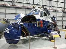
A major market for turboshaft engines is that for helicopters. When turboshaft engines became available in the 1950s, they were rapidly adopted for both new designs and as replacements for piston engines. They offered more power and far better power to weight ratios. Piston helicopters of this period had barely adequate performance; the switch to a turbine engine could both reduce several hundred pounds of engine weight, 600 lb (270 kg) for the Napier Gazelle of the Westland Wessex,[6] and also allow considerably more payload weight. For the Westland Whirlwind, this converted the inadequate piston-engined HAS.7 to the de Havilland Gnome turbine-powered HAR.9. As one of the first anti-submarine helicopters, the HAS.7 had been so restricted for weight that it could carry either a search sonar or an attack torpedo, but not both.
The free-turbine engine was particularly favoured. It did not require a clutch, as the gas generator could be spun up to operating speed without requiring the output shaft to rotate. For the Wessex this was used to give a particularly fast take-off from a cold start. By locking the main rotor (and the power turbine) with the rotor brake, the engine could be spun up to operating speed, then lit, and when the engine core is at the operating speed of 10,500 rpm the brake is released and drive to the rotor smoothly increased as the power turbine gains speed. This was used to bring the rotor to speed from stationary in just 15 seconds and a time from engine start to take-off of only 30 seconds.[6]
A further advantage of the free turbine design was the ease with which a counter-rotating engine could be designed and manufactured, simply by reversing the power turbine alone.[7] This allowed handed engines to be made in pairs, when needed. It also allowed contra-rotating engines, where gas generator core and power turbine revolved in opposite directions, reducing the overall moment of inertia. For the helicopter engine replacement market, this ability allowed previous engines of either direction to be replaced simply.[7] Some turboshaft engines' omni-angle freedom of their installation angle also allowed installation into existing helicopter designs, no matter how the previous engines had been arranged.[7] In time though, the move towards axial LP compressors and so smaller diameter engines encouraged a move to the now standard layout of one or two engines set side-by-side, horizontally above the cabin.
Aircraft
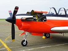
Turboprop aircraft are still powered by a range of free- and non-free turbine engines. Larger engines have mostly retained the non-free design, although many are two-shaft designs where the 'power' turbine drives the propellor and the low-pressure compressor, but the high-pressure compressor has its own turbine.
Some large turboprop engines, such as the original Bristol Proteus and the modern TP400 have free turbines. The TP400 is a three-shaft design, with two compressor turbines and a separate power turbine. Where the turbine is at the rear of the engine, a turboprop engine requires a long drive shaft forwards to the propeller reduction gearbox. Such long shafts can be a difficult design problem and must carefully control any shaft vibration.
For small turboprop engines, the free-turbine design has come to dominate and these designs are also mostly reversed overall, with their air inlet and compressor to the rear, feeding forwards to hot section and power turbine at the front. This places the turbine output close to the propeller gearbox, avoiding the need for a long drive shaft. Such engines are often recognisable externally, as they use external 'elbow' exhausts ahead of the main engine. A particularly common example of this is the PT6 engine, of which over 50,000 have been produced.
Pusher propfans

An attractively simple configuration making use of the free turbine is the propfan engine, with a rear-mounted unducted fan in pusher configuration, rather than the more familiar tractor layout. The first such engine was the very early and promising Metropolitan-Vickers F.3 of 1942 with a ducted fan, followed by the unducted and much lighter F.5. Development of these engines stopped abruptly owing to corporate takeovers, rather than technical reasons. Rolls-Royce continued with design studies for such engines into the 1980s,[8] as did GE, but they have yet to appear as commercial engines.[9]
The advantage of the pusher propfan with a free power turbine is its simplicity. The prop blades are attached directly to the outside of the rotating turbine disc. No gearboxes or drive shafts are required. The short length of the rotating components also reduces vibration. The static structure of the engine over this length is a large diameter tube within the turbine. In most designs, two contra-rotating rings of turbine and propeller are used. Intermeshed contra-rotating turbines can act as the guide vanes for each other, removing the need for static vanes.[8]
Land and sea
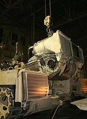
The M1 Abrams main battle tank is powered by a Honeywell AGT1500 (formerly Textron Lycoming) two-spool gas turbine engine. A commercial derivative has been designed as the TF15 for marine and railroad applications,[10][11] and a flight-rated version, the PLT27, was also developed but lost a major contract to the GE T700 turboshaft.[12]
Turboshaft engines were used to power several gas turbine locomotives, most notably using the Turbomeca Turmo in Turbotrain (France) and Turboliner (United States) service.
See also
References
- Gunston, Bill (2006) [1995]. The Development of Jet and Turbine Aero Engines (4th ed.). Patrick Stephens Limited. pp. 43–44. ISBN 978-1-85260-618-3.CS1 maint: ref=harv (link)
- Parsons, Dan (18 March 2015). "Industry asks US Army, one shaft or two for new helicopter engine". FlightGlobal. Retrieved 30 March 2020.
- Ehrich, Frederic F. (March 5–9, 1961). Design and Development Review of the T64 Turboprop/Turboshaft Engine (PDF). Gas Turbine Power Conference and Exhibit. Washington, D.C.: The American Society of Mechanical Engineers.
- "History of Romeo X-Ray". Britannia Aircraft Preservation Trust.
- "Accident description – G-ALRX". Aviation Safety Network.
- "Wessex". Flight. 29 November 1957. p. 838.
- "Aero Engines 1957". Flight. 26 July 1957. p. 118.
- The Jet Engine (4th ed.). Rolls-Royce plc. 1986. pp. 6, 53–54. ISBN 0-902121-04-9.
- "Whatever happened to propfans?". Flight. 12 June 2007.
- Lauriat, T.B. (June 8–12, 1986). The AVCO-Lycoming TF15: A Regenerative Marine Gas Turbine (PDF). International Gas Turbine Conference and Exhibit. Dusseldorf, Germany: The American Society of Mechanical Engineers.
- Horan, Richard (June 1–4, 1992). Textron Lycoming AGT1500 Engine—Transitioning for Future Applications (PDF). International Gas Turbine and Aeroengine Congress and Exposition. Cologne, Germany: The American Society of Mechanical Engineers.
- Leyes, Richard A.; Fleming, William A. (1999). The History of North American Small Gas Turbine Aircraft Engines. Reston, Virginia: American Institute of Aeronautics and Astronautics, Inc. pp. 218–222. ISBN 1-56347-332-1. Retrieved 30 March 2020.