Crimp (electrical)
An electrical crimp is a type of solderless electrical connection.
Crimp connectors are typically used to terminate stranded wire.[1] The benefits of crimping over soldering and wire wrapping include:
- A well-engineered and well-executed crimp is designed to be gas-tight, which prevents oxygen and moisture from reaching the metals (which are often different metals) and causing corrosion
- Because no alloy is used (as in solder) the joint is mechanically stronger[2]
- Crimped connections can be used for cables of both small and large cross-sections, whereas only small cross-section wires can be used with wire wrap[2][3]
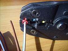
Crimping is normally performed by first inserting the terminal into the crimp tool. The terminal must be placed into the appropriately sized crimp barrel. The wire is then inserted into the terminal with the end of the wire flush with the exit of the terminal to maximize cross-sectional contact. Finally, the handles of the crimp tool are used to compress and reshape the terminal until it is cold-welded onto the wire.[3]
The resulting connection may appear loose at the edges of the terminal, but this is desirable so as to not have sharp edges that could cut the outer strands of the wire. If executed properly, the middle of the crimp will be swaged or cold-formed.
More specialized crimp connectors are also used, for example as signal connectors on coaxial cables in applications at high radio frequencies (VHF, UHF) .
Crimped contacts are permanent (i.e. the connectors and wire ends cannot be reused).[5]
History
The technique of soldering wires has remained common for at least a century, however crimp terminals came into use in the middle of the 20th century. In 1953, AMP Incorporated (now TE Connectivity) introduced crimp barrel terminals, and in 1957 Cannon Brothers experimented with machined contacts integrating crimp barrels.[6] During the 1960s, several standards for crimp connectors were published, including MS3191-1, MS3191-4 and MIL-T-22520. In 2010, the predominant standard for crimp connectors changed to MIL-DTL-22520.[7]
Theory
Crimp-on connectors are attached by inserting the stripped end of a stranded wire into a portion of the connector, which is then mechanically deformed by compressing (crimping) it tightly around the wire.[8] The crimping is usually accomplished with special crimping tool such as crimping pliers. A key idea behind crimped connectors is that the finished connection should be gas-tight.
Effective crimp connections deform the metal of the connector past its yield point so that the compressed wire causes tension in the surrounding connector, and these forces counter each other to create a high degree of static friction which holds the cable in place. Due to the elastic nature of the metal in crimped connections, they are highly resistant to vibration and thermal shock.[9]
Two main classes of wire crimps exist:[10]
- Closed barrel crimps have a cylindrical opening for a wire, and the crimping tool deforms the originally circular cross section of the terminal into some other shape . This method of crimping is less resilient to vibration.
- Open barrel crimps have "ears" of metal that are shaped like a V or U, and the crimp terminal bends and folds them over the wire prior to swaging the wire to the terminal. Open-barrel terminals are claimed to be easier to automate because of avoiding the need to funnel stranded wire into the narrow opening of a barrel terminal.
In addition to their shape, crimped connectors can also be characterized by their insulation (insulated or non-insulated), and whether they crimp onto the conductor(s) of a wire (wire crimp) or its insulation (insulation crimp).[11]
Crimp shapes
- C crimp[12]
- D crimp[13]
- F crimp[12][13] (a.k.a. B crimp)
- O crimp[14]
- W crimp[14][15]
- Overlap/OVL crimp[14]
- Oval (confined) crimp[14]
- Four-Mandrel crimp[14]
- Mandrel (crescent) crimp[14]
- Mandrel crimp-narrow (indented)[15]
- Hexagonal crimp[14][16]
- Mandrel (indent) crimp
- Square crimp[14][16]
- Trapezoidal crimp[14][16]
- Trapezoidal indent crimp[16]
- Trapezoidal crimp front[15]
- Tyco crimp[15]
- Western crimp
Applications
Crimped connections are common alternatives to soldered connections. There are complex considerations for determining which method is appropriate – crimp connections are sometimes preferred for these reasons:
- Easier, cheaper, or faster to reproduce reliably in large-scale production
- Fewer dangerous or harmful processes involved in termination (soldered connections require aggressive cleaning, high heat, and possibly toxic solders)
- Potentially superior mechanical characteristics due to strain relief and lack of solder wicking
Crimped connectors fulfill numerous uses, including termination of wires to screw terminals, blade terminals, ring/spade terminals, wire splices, or various combinations of these. A tube-shaped connector with two crimps for splicing wires in-line is called a butt splice connector.
Single-wire crimp terminals
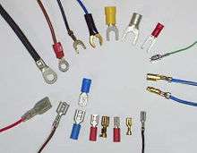
- Blade or quick disconnect (e.g. Faston or Lucar)
- Bullet (e.g. Shur-Plug)
- Butt splice
- Flag tongue
- Rectangular tongue
- Hook tongue
- Spade tongue (flanged, short spring, long spring)
- Ring tongue (slotted, offset)
- Multiple stud
- Packard 56
- Pin (SAE/J928)[17]
- Wire pin
Multipin connectors
Crimping is also a common technique to join wires to a multipin connector, such as in Molex connectors or modular connectors.
Crimp plug-and-socket connectors can be classified as rear release or front release, referring to the side of the connector where the pins are anchored:[18]
- Front release contacts are released from the front (contact side) of the connector, and removed from the rear. The removal tool engages with the front portion of the contact and pushes it through to the back of the connector.
- Rear release contacts are released and removed from the rear (wire side) of the connector. The removal tool releases the contacts from the rear and pulls the contact out of the retainer.
Coaxial connectors
Crimp connections are used typically to fix connectors, such as BNC connectors, to coaxial cables[19] quickly, as an alternative to soldered connections. Typically the male connector is crimp-fitted to a cable, and the female attached, often using soldered connections, to a panel on equipment. A special power or manual tool[20] is used to fit the connector. Wire strippers which strip outer jacket, shield braid, and inner insulation to the correct lengths in one operation[21] are used to prepare the cable for crimping.
Judging crimp quality
A crimped connection will only be reliable if a number of criteria are met:
- All strands have been deformed enough, into roughly a trapezoidal shape, to cold-flow into the terminal body[22]
- The compression force is not too light, nor too strong[23]
- The connector body is not overly deformed
- Wires must be in solid working condition, cannot have scrapes, nicks, severing or other damages
- Insulation should not show any signs of pinching, pulling, fraying, discoloration, or charring [24]
- Large voids are not left inside the crimp (caused by not enough wire inside the connector)
- The wire should have as many strands as possible, so that a few damaged or uninserted wires will not adversely affect the crimp density, and thus degrade the electrical and mechanical properties of the connection.[2]
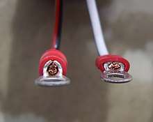
Micrographs of the crimped connections can be prepared to illustrate good and bad crimps for training and quality assurance purposes. The assembled connection is cut in cross-section, polished and washed in nitric acid to dissolve any copper dust that may be filling voids leading to a false indication of a good crimp.
Crimp tools
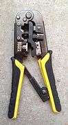
A wide variety of crimping tools exist, and they are generally designed for a specific type and size of terminal. Handheld tools (sometimes called crimping pliers) are most common, which may be ratcheting. For mass production operations, automated devices are available.[3]
 Klein modular connector crimpers
 Klein Journeyman crimpers
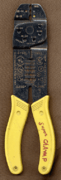 Crimping pliers, which can also strip and cut wire
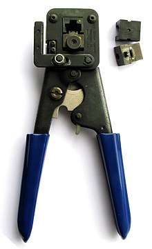 Crimping tool for modular connectors
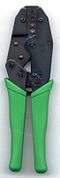 Crimping tool for F connectors and other hexagonal connectors
Terminal insulation colors
| Insulation color | Wire gauge (AWG) | Comments |
|---|---|---|
| Yellow | 26–22 | |
| Transparent | 24–20 | |
| Red | 22–18 | |
| Blue | 16–14 | |
| Yellow/Black | 16–14 | Heavy duty |
| Yellow | 12–10 | |
| Red | 8 | |
| Blue | 6 | |
| Yellow | 4 | |
| Red | 2 | |
| Blue | 1/0 | |
| Yellow | 2/0 | |
| Red | 3/0 | |
| Blue | 4/0 |
References
- Mazda, F. F. (2013-10-22). Electronics Engineer's Reference Book. Butterworth-Heinemann. ISBN 9781483161068. Archived from the original on 2018-01-22.
- "Crimped Joints". Archived from the original on 2018-01-22.
- Quality Crimping Handbook (PDF). Molex Application Tooling Group. 1996.
- "Jameco Catalog". jameco.com. Retrieved 21 March 2018.
- "Crimp vs. Solder" (PDF). Aviel Electronics Catalog. 2013. Retrieved 1 July 2019.
- "Crimping Facts". Archived from the original on 13 May 2015. Retrieved 11 July 2015.
- "MIL-DTL-22520: Crimping Tools, Wire Termination, General Specification for". Archived from the original on 1 December 2017. Retrieved 11 July 2015.
- Elliott, Brian (2007). Electromechanical devices & components illustrated sourcebook. McGraw-Hill. pp. 151. ISBN 978-0-07-147752-9.
- "Crimp vs Solder: Pros and Cons". RF Connectors. 1 December 2004. Retrieved 7 July 2019.
- XJ4Ever; Schmuckatelli Heavy Industries. "You're, like, crimping my style, man" (PDF). Retrieved 7 July 2019.
- "Crimp Quality Guidelines" (PDF). TE Connectivity Application Tooling. May 2011. Archived from the original (PDF) on 2 July 2013. Retrieved 7 July 2019.
- "Electronic Installation Practices Manual". NAVSHIPS 900171 (U.S. Navy). 23 May 1952. Archived from the original on 13 July 2015. Retrieved 12 July 2015.
- "2.8 mm Apex Terminal Crimp Guidelines" (PDF). Archived from the original (PDF) on 14 July 2015. Retrieved 12 July 2015.
- "Crimp symbols". Archived from the original on 2015-07-12.
- "Forms of Crimping". Archived from the original on 2017-11-17.
- "Ferrules: Your Best Insurance Against Costly Connection Failure" (PDF). Archived (PDF) from the original on 2017-12-01.
- "Electrical Terminals - Pin and Receptacle Type". Archived from the original on 12 July 2015. Retrieved 11 July 2015.
- Worley, Jon (31 July 2018). "Circular Connector Terminology Guide". NYK Component Solutions. Retrieved 7 July 2019.
- Typical crimp BNC connector
- Typical manual crimp tool for fitting BNC and other coaxial connectors to cables Archived 2014-10-29 at the Wayback Machine
- Typical coax one-operation stripper Archived 2014-10-29 at the Wayback Machine
- "Cross Sectioning". Archived from the original on 2017-06-20.
- "Tensile Test". Archived from the original on 2017-12-01.
- Wire Harness Manufacturing Terms, Tools, and Tips of the Trade
- "AMP Standard Terminals and Splices" (PDF). Archived (PDF) from the original on 2015-07-13.