9 track tape
The IBM System/360, released in 1964, introduced what is now generally known as 9 track tape. The ½ inch (12.7 mm) wide magnetic tape media and reels are the same size as the earlier IBM 7 track format it replaced, but the new format has eight data tracks and one parity track for a total of nine parallel tracks. Data is stored as 8-bit characters, spanning the full width of the tape (including the parity bit). Various recording methods were employed during its lifetime as tape speed and data density increased, including PE (phase encoding), GCR (group coded recording) and NRZI (non-return-to-zero, inverted, sometimes pronounced "nur-zee"). Tapes came in various sizes up to 3,600 feet (1,100 m) in length.
The standard size of a byte was effectively set at eight bits with the S/360 and nine-track tape.
For over 30 years the format dominated offline storage and data transfer, but by the end of the 20th century it was obsolete, and the last manufacturer of tapes ceased production in early 2002,[1] with drive production ending the next year.[2]
Typical operation
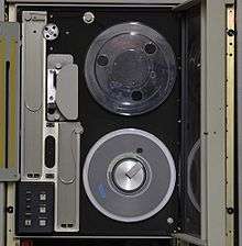
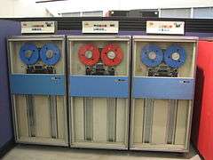
A typical 9-track unit consisted of a tape transport—essentially all the mechanics that moved tape from reel to reel past the read/write and erase heads—and supporting control and data read/write electronics. The transport typically consisted of supply motor, take-up motor, hubs for locking the tape reels in place, a capstan motor (though not necessarily a pinch roller, see below), tape head assembly, miscellaneous rollers which kept the tape in a precise path during operation, and vacuum columns which prevented tape 'snatch'. Data could become corrupted by stretched tape or variations in tape speed, so the transport had to guide the tape through without damaging its edges, move it with minimal wow and flutter, and give it a tension that was low but sufficient to keep the tape in constant contact with the read/write head.
To load a tape, an operator would remove the protective ring (frequently called a "tape seal belt" because its purpose was to prevent humidity and dust on the media) from the outside of the tape reel and install the tape on the supply hub, then thread the tape leader through the various roller assemblies and onto the take-up reel, installing three or four winds of tape to provide enough friction for the take-up motor to be able to pull the tape. The operator then initiated an automatic sequence, often by a single press of a button, that would start the vacuum system, then move the tape forward until the beginning-of-tape (BOT) foil strip was detected by an optical sensor in the tape path. The control electronics would then indicate to the controlling computer that the unit was ready for operation.
Like its audio counterpart, moving tape past the read/write heads on nine-track digital required precise control, accomplished by a capstan motor. The capstan motor was designed for very smooth operation. Feedback to the control electronics was accomplished by a tachometer, usually an optical "tone wheel", to control tape velocity. Starting and stopping the capstan was controlled by ramp generators to ensure a properly sized inter-record gap, the gap between blocks of information.
The vacuum system provided a physical buffer between the precision movements of the capstan and the large movements of the reels by storing a short length of tape in the vacuum column under relatively low tension. The vacuum columns were chambers open at one end, the openings being in line with the tape path before and after the capstan and roller assemblies. The amount of tape in the column was controlled by four optical or vacuum sensors on the sides of the columns. The control electronics kept the curve of the tape loop between the two inner sensors, cueing the supply reel to feed more or the take-up reel to take more as necessary. The outer two sensors, at the very top and bottom of the columns, served to sense malfunctions in the feed mechanism during operation, prompting the control electronics to shut off all operation of the tape transport and vacuum system to prevent damaging the tape. Because of the tension provided by the vacuum columns and the design of the tape path, tape was usually kept in sufficient contact with the relatively high-friction coating on the capstan that a pinch roller was not used.
Tape motion on many systems was bidirectional, i.e. tape could be read either forward or backward at the request of the controlling computer. Because the supply vacuum column kept a small, constant tension in the reverse direction, the capstan could feed backwards without the tape bunching up or jumping out of path. Unlike most audio tape systems, the capstan and head assemblies were always in contact with the tape, even during fast forward and reverse operations, only moving the head assembly away from the tape path during high-speed rewind. On some units, manufacturers installed a "fast search" capability which could move the tape quickly a certain number of blocks, then bring the tape to a halt and go back to read the requested data at normal speed.
Tapes included an end-of-tape (EOT) foil strip. When EOT was encountered while writing, the computer program would be notified of the condition. This gave the program a chance to write end-of-tape information on the tape while there was still enough tape to do so.
The sensing of BOT and EOT was achieved by shining a small lamp at the tape's surface at an oblique angle. When the foil strip (glued to the tape) moved past the lamp a photo-receptor would see the reflected flash of light and trigger the system to halt tape motion. This is the main reason that photographic flash cameras were not allowed in data centers since they could (and did) trick the tape drives into falsely sensing BOT and EOT.[3]
The above describes a typical transport system; however, manufacturers engineered many alternative designs. For example, some designs used a horizontal transport deck where the operator simply set the tape reel in the supply reel bay, closed the door and pressed the load button, then a vacuum system would draw the tape along the path and onto a take-up hub within the mechanism. Some designs eliminated the vacuum columns in favor of a microprocessor-controlled direct drive design.
Technical details
9-track 800 NRZI and 1600 PE (phase encoding) tapes use a 0.6 inches (15 mm) inter-record gap (IRG) between data records to allow the tape to stop and start between records. 6250 GCR tapes use a tighter 0.3 inches (7.6 mm) IRG.
The 9-track tapes had reflective stickers placed on the non-data side 10 feet (3.0 m) from the beginning of the tape and 14 feet (4.3 m) from the end of the tape to facilitate signaling the hardware to prevent the tape from unwinding from the hubs. These reflective stickers established the beginning-of-tape (BOT) and end-of-tape (EOT) marks. Ten feet of leader and trailer tape was sufficiently long to allow the tape down and up the air columns and wrap around the hub a few times. The extra 4 feet in the trailer was to allow the operating system space to write a few blocks of data after the EOT mark to finalize the tape data segment in a multi-volume dataset. It was a common practice for operators to clip off a few inches of leader tape when it became frayed. If the leading reflective strip became detached from the tape it became very difficult to read the data since the BOT point of the dataset was no longer easily located and BOT orientation was nearly impossible.
Nine-track tapes commonly had densities of 800, 1600, and 6250 cpi, giving 22.5MB, 45MB and 175MB respectively on a standard 2,400 feet (730 m) tape.
IBM generations
| IBM Model | 2400 Series | 3400 Series |
|---|---|---|
| Model numbers | 2401, 2415, 2420 | 3410, 3420, 3422, 3440 |
| Density (bits/in/track) | 800, 1600 | 800, 1600, 6250 |
| Tape speed (in/s) | 18.75–200 | 120–200 |
| Transfer rate (B/s) | 15,000–320,000 | 1,250,000 |
| Interblock gap (in) | 0.6 | 0.3 |
| Rewind speed (in/s, avg.) | ||
| Start time (ms) | ||
| Stop time (ms) | ||
| Length of reel (ft) | 2400 max | 2400 max |
| Base composition | Plastic | Plastic |
2400 Series
The 2400 Series Magnetic Tape Units were introduced with the System/360 and were the first to use 9 track tape. The dimensions of the tape and reels were identical to those used with 7 track units, such as the IBM 729. But older 7 track tapes could be read and written only on special 2400 drives equipped with 7 track read and write heads and the 7 track compatibility option.
3400 Series
The 3400 Series Magnetic Tape Units were introduced with the IBM System/370. The primary advantages of the 3400 system were the higher data density (6250 BPI) and support of the "autoloader" cartridge, first seen in the IBM 2420 model 7. Prior to the autoloader cartridge, tapes were sealed in a plastic "tape seal belt" that surrounded the reel and provided contamination protection and rack-hanging capability. The 3420's autoloader cartridge enabled the tape operator to mount the reel directly on the hub without having to remove the seal belt. This provided a significant time saving and reduced operator errors since the operator did not have to remove/replace the belt or thread the tape onto the take-up reel.
Other IBM Tape Units
While the earlier tape drives had vacuum columns, some IBM tape drives such as the 8809 drive (1980's) was a flat mount situation and no vacuum columns existed. Tapes were manually mounted and threaded. The drive supported both 800 and 1600 bpi. This drive was used on the IBM System/36. On the IBM as/400/iseries there was the 9348-012 and it was a table top drive, again flat mounting, but it autoloaded the tape reel and auto threaded it. The 9348 supported 1600 and 6250 bpi density tapes.
Other Information
The maximum data capacity of a 2400 ft reel, with 32,767 byte blocks and recorded at 6250 BPI was 170 megabytes. Typically, much smaller block sizes, such as 4K (4,096 bytes) were used, in which case the storage capacity of the tape was reduced to 113 megabytes.
Depending on the operating system, tapes were formatted as either EBCDIC (if IBM equipment was used) or ASCII, and were either "labeled" (if the data was preceded by a tape header, typically containing a tape name and date), "unlabeled" (if the tape contained no header) or had a "non-standard label" (the tape had a header, but it did not conform to the format expected by the equipment used to read the tape).
Data was often written to the tape in blocks, instead of one record at a time. Between blocks, there was an interblock gap, which varied depending on the density, but was typically 5/8 to 3/4 of an inch long. To maximize the amount of data that was stored on a tape, the number of gaps had to be minimized. Additionally, data stored in blocks could be read and written to more quickly than data stored one record at a time. The disadvantage, however, was that data corruption within a block could cause multiple records to be lost.
Examples
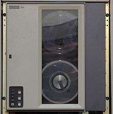
 Full size 1/2" tape reel in protective case.
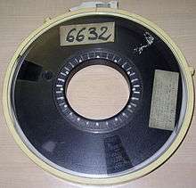
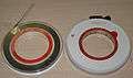 Two small 1/2" tapes, front and back.
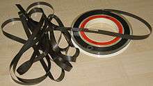 Aluminum foil strips marked the start and end of tape.
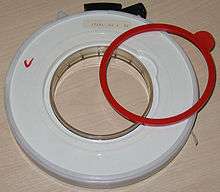 The write protection ring prevented the tape from being written on when removed.
 A typical library of half-inch magnetic tape
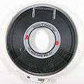 3M 777 High Grade 6250 CPI - Security Computer Tape
Standards
- ANSI INCITS 40-1993 (R2003) Unrecorded Magnetic Tape for Information Interchange (9-Track, 800 CPI, NRZI; 1600 CPI, PE; and 6250 CPI, GCR)
- ISO/IEC 1863:1990 9-track, 12.7 mm (½ in) wide magnetic tape for information interchange using NRZ1 at 32 ftpmm (800 ftpi) — 32 cpmm (800 cpi)
- ISO/IEC 3788:1990 9-track, 12.7 mm (½ in) wide magnetic tape for information interchange using phase encoding at 126 ftpmm (3 200 ftpi), 63 cpmm (1600 cpi)
- ANSI INCITS 54-1986 (R2002) Recorded Magnetic Tape for Information Interchange (6250 CPI, Group Coded Recording)
- ANSI INCITS 27-1987 (R2003) Magnetic Tape Labels and File Structure for Information Interchange
Other drive manufacturers
- Ampex
- Anritsu
- Burroughs
- Cipher Data Products
- Control Data
- Digi-Data
- Fujitsu
- Hewlett-Packard (incl. Dynec/Dymec)
- Kennedy
- Innovative Data Technology (IDT/Alston)
- Laser Magnetic Storage / Philips LMS / Plasmon LMS
- M4 Data
- Overland Data
- PerkinElmer
- Pertec Computer
- Qualstar
- SE Labs (EMI)
- STC / Storage Technology Corp, (then: StorageTek (STK) after name change), (acquired by SUN, now a division of Oracle Corp).
- Wangco
Media manufacturers
- 3M now Imation — The first manufacturer of 9 track tape.
- Graham Magnetics — The last manufacturer to produce new 9-track tape (2001).
References
- "eMag Solutions LLC announces end-of-life plan for open reel (9-track) tape". eMag Solutions. 2001-12-17. Archived from the original on 2001-12-28. Retrieved 2016-03-19.
- "Qualstar Bids Farewell to 9-Track Tape Drives". Business Wire. 2003-09-22. Archived from the original on 2016-01-17. Retrieved 2016-03-19.
- Howard C. Berkowitz (1987-06-04), "BBC documentary filming causes Library of Congress computer crashes", RISKS Digest, 5 (5), retrieved 2009-03-15
External links
| Wikimedia Commons has media related to Half inch magnetic tapes. |
- IBM 3420 magnetic tape drive from the IBM archives.
- At bitsavers.org
- Cipher documentation
- DEC TS11 TU80 (1600 PE) TA78 TA79 TU81(1600 PE, 6250 GCR)
- Fujitsu M244x Tape Drive CE Manual
- HP 7970 Maintenance Course Handouts: 800 NRZI & 1600 PE drives
- IBM 2400 Series Tape Drives Component Description
- Kennedy tape models
- M4Data documentation
- Univac UNISERVO IIIA, IIIC Magnetic Tape Subsystem Technical Bulletins
- HP 7976A 7978A 7980A (88780AB) (1600 PE, 6250 GCR) HP 7974A 1600 PE at hpmuseum.net
- Dong JW, Proehl KA, Abramson RL, Christie LG, Domel DR (June 1988). "A reliable, autoloading, streaming half-inch tape drive". Hewlett-Packard Journal. 39 (3). (7980A, 88780AB)
- IBM 9348-012 (1600, 6250)
- Brochures for M4 Data 9906 1600, (-2 → 3200, -5 → 6250), 9914, 9914V (800, 1600, 3200, 6250)
- Qualstar 3400 Series
- Timeline of OEM drive manufacturers
- 9 track tape drives at Columbia University, c. 1982