UHF connector
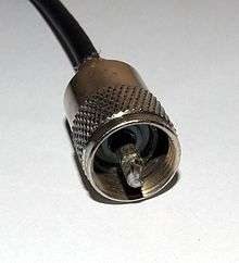
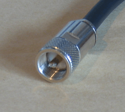 PL-259 (male) plug. Outside diameter is about 18 mm. | |||
| Type | RF coaxial connector | ||
|---|---|---|---|
| Production history | |||
| Designed | 1930s | ||
| Manufacturer | Various | ||
| General specifications | |||
| Diameter | 18 mm (0.71 in) (typical) | ||
| Cable | Coaxial | ||
| Passband | Typically 0–100 MHz[1] | ||
| Connector |
SO-239 (socket)[2] PL-259 (plug) [3] | ||
| Electrical | |||
| Signal | Non-constant impedance[4] | ||
| Max. voltage | 500 volts peak[4] | ||

The UHF connector[4] is a dated name for a threaded RF connector. [5][6] The connector design was invented in the 1930s for use in the radio industry, and is a shielded form of the "banana plug".[7][8][4] It is a widely-used standard connector for HF transmission lines on full-sized radio equipment, with BNC connectors predominating for smaller, hand-held equipment.[8]
The name "UHF" is a source of legitimate confusion, since the name of the connectors did not change when the frequency-ranges were renamed. The design was named during an era when "UHF" meant frequencies over 30 MHz.[9][10][11] Today Ultra high frequency (UHF) instead refers to frequencies between 300 MHz and 3 GHz[lower-alpha 1] and the range of frequencies formerly known as UHF is now called "VHF". Further adding to the confusion, the so-called "UHF" connectors are only well suited for the lower-VHF range and lower; they perform poorly for the higher modern UHF region.[8][1] A more appropriate name would be "HF" connectors.
There is no active specification or standard governing the mechanical and electrical characteristics of the so-called "UHF" connector system making it effectively a deprecated design..
Other names
The connector reliably carries signals at frequencies up to 100 MHz.[1] The coupling shell has a 5⁄8 inch 24 tpi UNEF standard thread.[4] The most popular cable plug and corresponding chassis-mount socket carry the old Signal Corps nomenclatures PL-259 (plug) and SO-239 (socket).[12] These are also known as Navy type 49190 and 49194 respectively.[13]
PL-259, SO-239, PL-258, and several other related military references refer to one specific mechanical design collectively known as the UHF Connector.[4] In some countries, for example in Israel, the term 'PL connector' is confusingly associated rather with the analog phone connector. The designations come from the Joint Electronics Type Designation System, its predecessor AN system, and the earlier SCR (Set, Complete, Radio) system.[14]
Characteristics
Mechanical
By design, all connectors in the UHF connector family mate using the 5⁄8 inch 24 tpi threaded shell for the shield connection[4] and an approximately 0.156 inch-diameter (4 mm) pin and socket for the inner conductor. Similar connectors with an incompatible 16 mm diameter, 1 mm metric thread have been produced,[15] but these are not standard UHF connectors by definition.[4]
Surge impedance
UHF connectors have a non-constant surge impedance.[4] For this reason, UHF connectors are generally usable through HF and the lower portion of what is now known as the VHF frequency range.[1] Despite the name, the UHF connector is rarely used in commercial applications for today's UHF frequencies, as the non-constant surge impedance creates measurable electrical signal reflections above 100 MHz.[1][16][17]
Virtually all of the impedance bump and loss is in the UHF female. A typical SO-239 UHF female, properly hooded, has an impedance bump of about 35 Ohms. The length of the bump is typically 1⁄2 inch, where the female pin flares to fit over the male pin.This bump can be mitigated by using a honeycomb dielectric in the female pin area. Many VHF/UHF amateur operators use special UHF females that maintain a 50 Ohm surge impedance.[18]
Power
Better quality UHF connectors can handle RF peak power levels well over one kilowatt based on the voltage rating of 500 Volts peak.[4] In practice, a better quality UHF connector will handle over 4 kV peak voltage. Manufacturers typically test UHF jumpers in the 3-5 kV range. UHF connectors are standard on HF amateur amplifiers rated at 1500+ Watts output.
In practice, voltage limit is set by the air gap between center and shield. The center pin diameter and contact area is large enough that pin heating in not an issue. UHF connectors are generally limited by cable heating rather than connector failure.
Environmental tolerance
Applications
In many applications, UHF connectors were replaced by designs that have a more uniform surge impedance over the length of the connector, such as the N connector and the BNC connector.[19] UHF connectors are still widely used in amateur radio, Citizens Band radio, and marine VHF radio applications.
See also
Notes
- ↑ "UHF" is 300 MHz and 3 GHz in both the ITU and IEEE radio band designation systems
References
- 1 2 3 4 5 "'UHF' connector". Connectors. Test results. Hamradio.me. October 2011. Retrieved 31 January 2012.
- ↑ US patent 2761110, Diambra, Henry M, "Solderless Coaxial Connector", published 1956-08-28, assigned to Entron Inc.
- ↑ US patent 4085366, Padgett, Billy, "Noise reduction device for citizen's band transceivers", published 1978-04-18, assigned to Billy Padgett
- 1 2 3 4 5 6 7 8 9 10 11 "UHF Connector Series". Amphenol. Retrieved 23 September 2015.
- ↑ US patent 2335041, "Right-angle electric connector", published 1943-11-23, assigned to Bruno Patents Inc
- ↑ US patent 2422982, Quackenbush, Edward Clarke, "Coaxial cable connector", published 1947-06-24, assigned to Quackenbush, Edward Clarke
- ↑ Henney, Keith (1941). "15". Radio Engineering Handbook (PDF) (Third ed.). New York, NY: McGraw-Hill Book Company. p. 514. Retrieved 12 September 2018.
- 1 2 3 4 Hallas, Joel R. (5 October 2012). Care and Feeding of Transmission Lines. Newington, CT: American Radio Relay League. ISBN 978-0872594784.
- ↑ Pollack, Dale (1941). "High-Frequency Transmission and Reception". In Henney, Keith. Radio Engineering Handbook (3rd ed.). New York; London: McGraw-Hill Book Company. p. 514.
- ↑ "(PL) 259 Connectors". Connectors. Hamradio.me. July 2011. Retrieved 16 May 2015.
- ↑ "Introduction to U.H.F.". The Radio Amateur's Handbook (18th ed.). West Hartford, CT: American Radio Relay League. 1941. pp. 362–363.
In Amateur work, the ultra-high-frequency region is considered to include the 56 to 60 MC band and all higher frequency bands available for amateur use.
- ↑ . Department of the Army. 23 April 1966. TM 11-5820-348-15. Text "title-Antenna Equipment RC-292 " ignored (help); Missing or empty
|title=(help) - ↑ Electronic Test Equipment. Military Standardization Handbook. I. Department of Defense. 11 March 1964. MIL-HDBK 172A.
- ↑ "Designations Of U.S. Military Electronic and Communications Equipment".
- ↑ "Drawing of metric connector". RF Supplier. Retrieved 24 September 2015.
- ↑ US patent 2233166, Hahn, William C., "Means for transferring high frequency power", published 1941-02-25, assigned to General Electric Co.
- ↑ "The UHF type connector under network analysis". Chris's Amateur Radio and Electronics resource pages. Retrieved 31 January 2012.
... at 432 MHz ... we see a loss in the order of 1.0 dB, this equates to a transmission loss of around 6 Watts with 25 Watts input.
- ↑ "A Look at the UHF Connector". Retrieved 16 September 2018.
- ↑ "SMA, BNC, TNC, and N Connectors". Lab Tests. Connectors. Hamradio.me. August 2011. Retrieved 31 January 2012.