Twisted pair
Twisted pair cabling is a type of wiring in which two conductors of a single circuit are twisted together for the purposes of improving electromagnetic compatibility. Compared to a single conductor or an untwisted balanced pair, a twisted pair reduces electromagnetic radiation from the pair and crosstalk between neighboring pairs and improves rejection of external electromagnetic interference. It was invented by Alexander Graham Bell.[1]
Explanation
In a balanced line, the two wires carry equal and opposite signals, and the destination detects the difference between the two. This is known as differential signaling. Noise sources introduce signals into the wires by coupling of electric or magnetic fields and tend to couple to both wires equally. The noise thus produces a common-mode signal which can be canceled at the receiver when the difference signal is taken.
Differential signaling starts to fail when the noise source is close to the signal wires; the closer wire will couple with the noise more strongly and the receiver will be unable to eliminate it. This problem is especially apparent in telecommunication cables where pairs in the same cable lie next to each other for many miles. Twisting the pairs counters this effect as on each half twist the wire nearest to the noise-source is exchanged. Provided the interfering source remains uniform, or nearly so, over the distance of a single twist, the induced noise will remain common-mode.
The twist rate (also called pitch of the twist, usually defined in twists per meter) makes up part of the specification for a given type of cable. When nearby pairs have equal twist rates, the same conductors of the different pairs may repeatedly lie next to each other, partially undoing the benefits of differential mode. For this reason it is commonly specified that, at least for cables containing small numbers of pairs, the twist rates must differ.[2]
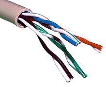
In contrast to shielded or foiled twisted pair (typically F/UTP or S/FTP cable shielding), UTP (unshielded twisted pair) cable is not surrounded by any shielding. UTP is the primary wire type for telephone usage and is very common for computer networking.
History
The earliest telephones used telegraph lines, or open-wire single-wire earth return circuits. In the 1880s electric trams were installed in many cities, which induced noise into these circuits. Lawsuits being unavailing, the telephone companies converted to balanced circuits, which had the incidental benefit of reducing attenuation, hence increasing range.
As electrical power distribution became more commonplace, this measure proved inadequate. Two wires, strung on either side of cross bars on utility poles, shared the route with electrical power lines. Within a few years, the growing use of electricity again brought an increase of interference, so engineers devised a method called wire transposition, to cancel out the interference.
In wire transposition, the wires exchange position once every several poles. In this way, the two wires would receive similar EMI from power lines. This represented an early implementation of twisting, with a twist rate of about four twists per kilometre, or six per mile. Such open-wire balanced lines with periodic transpositions still survive today in some rural areas.
Twisted-pair cabling was invented by Alexander Graham Bell in 1881.[3] By 1900, the entire American telephone line network was either twisted pair or open wire with transposition to guard against interference. Today, most of the millions of kilometres of twisted pairs in the world are outdoor landlines, owned by telephone companies, used for voice service, and only handled or even seen by telephone workers.
Unshielded twisted pair
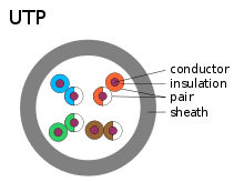
Unshielded twisted pair (UTP) cables are found in many Ethernet networks and telephone systems. For indoor telephone applications, UTP is often grouped into sets of 25 pairs according to a standard 25-pair color code originally developed by AT&T Corporation. A typical subset of these colors (white/blue, blue/white, white/orange, orange/white) shows up in most UTP cables. The cables are typically made with copper wires measured at 22 or 24 American Wire Gauge (AWG),[4] with the colored insulation typically made from an insulator such as polyethylene or FEP and the total package covered in a polyethylene jacket.
For urban outdoor telephone cables containing hundreds or thousands of pairs, the cable is divided into small but identical bundles. Each bundle consists of twisted pairs that have different twist rates. The bundles are in turn twisted together to make up the cable. Pairs having the same twist rate within the cable can still experience some degree of crosstalk. Wire pairs are selected carefully to minimize crosstalk within a large cable.
UTP cable is also the most common cable used in computer networking. Modern Ethernet, the most common data networking standard, can use UTP cables. Twisted pair cabling is often used in data networks for short and medium length connections because of its relatively lower costs compared to optical fiber and coaxial cable.
UTP is also finding increasing use in video applications, primarily in security cameras. Many cameras include a UTP output with screw terminals; UTP cable bandwidth has improved to match the baseband of television signals. As UTP is a balanced transmission line, a balun is needed to connect to unbalanced equipment, for example any using BNC connectors and designed for coaxial cable.
Cable shielding
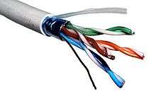

Twisted pair cables often incorporate shielding in an attempt to prevent electromagnetic interference. Shielding provides an electrically conductive barrier to attenuate electromagnetic waves external to the shield; and provides a conduction path by which induced currents can be circulated and returned to the source via ground reference connection.
Such shielding can be applied to individual pairs or quads; or to a collection of pairs. Individual pairs are foil shielded, while an overall cable (of multiple pairs) may use any of braided screen or foil or braiding with foil.
When shielding is applied to a collection of pairs, it is usually referred to as screening, but usage among vendors and authors in applying such words as screening, shielding, and STP (shielded twisted pair) can be subject to variability.[5][6]
ISO/IEC 11801:2002 (Annex E) attempts to internationally standardize the various designations for shielded cables by using combinations of three letters - U for unshielded, S for braided shielding (in outer layer only), and F for foil shielding - to explicitly indicate the type of screen for overall cable protection and for protecting individual pairs or quads, using a two-part abbreviation in the form of x/xTP.
Shielded Cat 5e, Cat 6/6A, and Cat 8/8.1 cables typically have F/UTP construction, while shielded Cat 7/7A and Cat 8.2 cables use S/FTP construction.[7]
Because the shielding is made of metal, it may also serve as a path to ground; usually a screen shielded, twisted pair cable has an integrally incorporated, grounding wire, called a drain wire, which makes electrical contact with the shield or screen. The purpose of the drain wire is for easy connection of the screen to terminals, which are usually designed for connection of round wires.
Common shield construction types include:
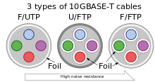
- Individual shield (U/FTP)
- Individual shielding with aluminum foil for each twisted pair or quad. Common names: pair in metal foil, shielded twisted pair, screened twisted pair. This type of shielding protects cable from external EMI entering or exiting the cable and also protects neighboring pairs from crosstalk.
- Overall shield (F/UTP, S/UTP, and SF/UTP)
- Overall foil, braided shield or braiding with foil across all of the pairs within the 100 ohm twisted pair cable. Common names: foiled twisted pair, shielded twisted pair, screened twisted pair. This type of shielding helps prevent EMI from entering or exiting the cable.
- Individual and overall shield (F/FTP, S/FTP, and SF/FTP)
- Individual shielding using foil between the twisted pair sets, and also an outer foil or braided shielding. Common names: fully shielded twisted pair, screened foiled twisted pair, shielded foiled twisted pair, screened shielded twisted pair, shielded screened twisted pair. This type of shielding helps prevent EMI from entering or exiting the cable and also protects neighboring pairs from crosstalk.
An early example of shielded twisted-pair was IBM STP-A, which is a two-pair 150 ohm S/FTP cable defined in 1985 by the IBM Cabling System specifications, and used with token ring or FDDI networks.[5][8]
| Industry abbreviations | ISO/IEC 11801 name | Cable shielding | Pair shielding |
|---|---|---|---|
| UTP | U/UTP | None | None |
| STP, ScTP, PiMF | U/FTP | None | Foil |
| FTP, STP, ScTP | F/UTP | Foil | None |
| STP, ScTP | S/UTP | Braiding | None |
| SFTP, S-FTP, STP | SF/UTP | Braiding and Foil | None |
| FFTP | F/FTP | Foil | Foil |
| SSTP, SFTP, STP PiMF | S/FTP | Braiding | Foil |
| SSTP, SFTP | SF/FTP | Braiding and Foil | Foil |
The code before the slash designates the shielding for the cable itself, while the code after the slash determines the shielding for the individual pairs:
- U = unshielded
- F = foil shielding
- S = braided shielding (outer layer only)
- TP = twisted pair
- TQ = twisted pair, individual shielding in quads
Common types
Analog telephone
Before digital communication and ethernet became widespread there was no international standard for telephone cable. Standards were set at a national level. For instance, in the UK the General Post Office specified CW1293 and CW1308 cables. CW1308 was a similar specification to the earlier CW1293 but with an improved color code. CW1293 used mostly solid colors on the cores making it difficult to identify the pair it was twisted with without stripping back a large amount of sheath. CW1308 has narrow rings of the paired color printed over the base color to solve this problem. Both cables are a similar standard to category 3 cable.[9]
Prior to the common use of polyethylene and other plastics for insulation, telephone twisted pair cable was insulated with waxed paper or cotton with a wax coating applied to the copper. The overall sheath of this type of cable was usually lead. This style of cable came into use in the late 19th century shortly after the invention of the telephone.[10] The cable termination in termination boxes were sealed with molten wax or epoxy resin to prevent the ingress of moisture which would seriously degrade the insulating properties of the paper insulation.[11] However, such seals made future maintenance and changes more difficult. These cables are no longer made, but are still occasionally encountered in old buildings and in various external areas, commonly rural villages.
Building infrastructure
| Name | Typical construction | Bandwidth | Applications | Notes |
|---|---|---|---|---|
| Level 1 | 0.4 MHz | Telephone and modem lines | Not described in EIA/TIA recommendations. Unsuitable for modern systems.[12] | |
| Level 2 | 4 MHz | Older terminal systems, e.g. IBM 3270 | Not described in EIA/TIA recommendations. Unsuitable for modern systems.[12] | |
| Cat 3 | UTP[13] | 16 MHz[13] | 10BASE-T and 100BASE-T4 Ethernet[13] | Described in EIA/TIA-568. Unsuitable for speeds above 16 Mbit/s. Now mainly for telephone cables[13] |
| Cat 4 | UTP[13] | 20 MHz[13] | 16 Mbit/s[13] Token Ring | Not commonly used[13] |
| Cat 5 | UTP[13] | 100 MHz[13] | 100BASE-TX & 1000BASE-T Ethernet[13] | Common for current LANs. Superseded by Cat5e, but most Cat5 cables meet Cat5e standards.[13] Limited to 100m between equipment. |
| Cat 5e | UTP[13] , STP[14] | 100 MHz[13] | 100BASE-TX & 1000BASE-T Ethernet[13] | Enhanced Cat5. Common for current LANs. Same construction as Cat5, but with better testing standards.[13] Limited to 100m between equipment. |
| Cat 6 | UTP[13] , STP[15] | 250 MHz[13] | 10GBASE-T Ethernet | ISO/IEC 11801 2nd Ed. (2002), ANSI/TIA 568-B.2-1. Most commonly installed cable in Finland according to the 2002 standard EN 50173-1. Limited to 55M distance at 10GBASE-T |
| Cat 6A | UTP, F/UTP, U/FTP | 500 MHz | 10GBASE-T Ethernet | Improved standards, tested to 500 MHz. Full 100M distance at 10GBASE-T ISO/IEC 11801 2nd Ed. Am. 2. (2008), ANSI/TIA-568-C.1 (2009) |
| Cat 7 | S/FTP, F/FTP | 600 MHz | 10GBASE-T Ethernet or POTS/CATV/1000BASE-T over single cable | Fully shielded cable. ISO/IEC 11801 2nd Ed. (2002). It is not recognized by the EIA/TIA. |
| Cat 7A | S/FTP, F/FTP | 1000 MHz | 10GBASE-T Ethernet or POTS/CATV/1000BASE-T over single cable | Uses all four pairs. ISO/IEC 11801 2nd Ed. Am. 2. (2008). It is not recognized by the EIA/TIA. |
| Cat 8/8.1 | F/UTP, U/FTP | 2000 MHz | 40GBASE-T Ethernet or POTS/CATV/1000BASE-T over single cable | ANSI/TIA-568-C.2-1, ISO/IEC 11801-1:2017 |
| Cat 8.2 | S/FTP, F/FTP | 2000 MHz | 40GBASE-T Ethernet or POTS/CATV/1000BASE-T over single cable | ISO/IEC 11801-1:2017 |
Solid-core cable vs. stranded cable
A solid-core cable uses one solid wire per conductor and in a four pair cable there would be a total of eight solid wires.[13] Stranded conductor uses multiple wires wrapped around each other in each conductor and in a four pair with seven strands per conductor cable, there would be a total of 56 wires (2 per pair × 4 pairs × 7 strands).[13]
Solid core cable is intended for permanently installed runs. It is less flexible than stranded cable and is more prone to failure if repeatedly flexed. Stranded cable is used for fly leads at patch panel and for connections from wall-ports to end devices, as it resists cracking of the conductors.
Connectors are designed differently for solid core than for stranded. Use of a connector with the wrong cable type can lead to unreliable cabling. Plugs designed for solid and stranded core are readily available, and some vendors even offer plugs designed for use with both types. The punch-down blocks on patch-panel and wall-port jacks are designed for use with solid core cable, these work via a method known as insulation-displacement which pierces the sides of the insulation and "bites" in to the copper conductor to form a connection.
Advantages
Disadvantages
- Deformation: twisted pair's susceptibility to electromagnetic interference greatly depends on the pair twisting schemes (sometimes patented by the manufacturers) staying intact during the installation. As a result, twisted pair cables usually have stringent requirements for maximum pulling tension as well as minimum bend radius. This fragility of twisted pair cables makes the installation practices an important part of ensuring the cable's performance.[17]
- Delay skew: different pairs within the cable have different delays, due to different twist rates used to minimize crosstalk between the pairs. This can degrade image quality when multiple pairs are used to carry components of a video signal. Low skew cable is available to mitigate this problem.[18][19]
- Imbalance: differences between the two wires in a pair can cause coupling between the common mode and the differential mode. Differential to common mode conversion produces common mode currents that can cause external interference and can produce common mode signals in other pairs. Common mode to differential mode conversion can produce differential mode signals from common mode interference from other pairs or external sources. Imbalance can be caused by asymmetry between the two conductors of the pair from each other and in relationship to other wires and the shield. Some sources of asymmetry are differences in conductor diameter and insulation thickness. In telephone jargon, the common mode is called longitudinal and the differential mode is called metallic.[20]
Less common variants
- Loaded twisted pair
- A twisted pair that has intentionally added inductance, formerly common practice on telecommunication lines. The added inductors are known as load coils and reduce attenuation for voiceband frequencies but increase it on higher frequencies. Load coils reduce distortion in voiceband on very long lines.[21] In this context a line without load coils is referred to as an unloaded line.
- Bonded twisted pair
- A twisted pair variant in which the pairs are individually bonded to increase robustness of the cable. Pioneered by Belden, it means the electrical specifications of the cable are maintained despite rough handling.[22]
- Twisted ribbon cable
- A variant of standard ribbon cable in which adjacent pairs of conductors are bonded and twisted together. The twisted pairs are then lightly bonded to each other in a ribbon format. Periodically along the ribbon there are short sections with no twisting to enable connectors and PCB headers to be terminated using the usual ribbon cable IDC techniques.[23]
See also
- Ethernet over twisted pair
- Balanced line
- Copper wire and cable
- Litz wire
- Registered jack
- Star quad cable increases cancellation of interference
- TIA/EIA-568-B
- Tip and ring
References
- ↑ McBee, David Barnett, David Groth, Jim (2004). Cabling : the complete guide to network wiring (3rd ed.). San Francisco: SYBEX. p. 11. ISBN 9780782143317.
- ↑ "Crosstalk dependence on number of turns/inch for twisted pair versions of the end-cap umbilical cable" (PDF).
- ↑ US 244426, Bell, Alexander Graham, "Telephone-circuit", issued 1881. See also TIFF format scans for USPTO 00244426
- ↑ Steven T. Karris (2009). Networks: Design and Management. Orchard Publications. p. 6. ISBN 978-1-934404-15-7.
- 1 2 Anitech Systems MP 4000 Manual
- ↑ Grounding for Screened and Shielded Network Cabling - Siemon
- ↑ Valerie, Maguire (2015-07-12). "Size of the Category 7A Installed Base" (PDF). Retrieved 2015-09-25.
- ↑ http://www.techfest.com/networking/cabling/ibmcs.htm
- ↑ Stephen Roberts, Telephone Installation Handbook, pp. 32-34, Elsevier, 2001 ISBN 0080521487.
- Barry J. Elliot, Designing a Structured Cabling System to ISO 11801, p. 269, CRC Press, 2002 ISBN 0824741307.
- ↑ Telephony, vol. 153, p. 118, Telephone Publishing Corporation 1957.
- ↑ Paper Maker and British Paper Trade Journal, vol. 83-84, p. 294, November 1, 1932 OCLC 10634178
- 1 2 "CCNA: Network Media Types".
- 1 2 3 4 5 6 7 8 9 10 11 12 13 14 15 16 17 18 19 20 "Comparison between CAT5, CAT5e, CAT6, CAT7 Cables".
- ↑ "Using UTP Cat5e vs. STP Cat5e Cable - SewellDirect.com". sewelldirect.com. Retrieved 2018-08-19.
- ↑ "CAT3 vs. CAT5 vs. CAT6 - CustomCable". CustomCable. 2011-12-24. Retrieved 2018-08-19.
- 1 2 3 4 "Twisted Pair Testing".
- ↑ "The Impact of Installation Stresses On Cable Performance" (PDF). Belden. Retrieved 13 August 2016.
- ↑ "7987R Technical Data Sheet (Metric)" (PDF). Belden.com. Belden. Retrieved 13 August 2016.
- ↑ "7989R Technical Data Sheet (Metric)" (PDF). Belden.com. Belden. Retrieved 13 August 2016.
- ↑ Reeve, Whitman D. (1995). Subscriber Loop Signaling and Transmission Handbook - Digital (1st ed.). IEEE Press. pp. 215–220. ISBN 0-7803-0440-3.
- ↑ "Understanding Line Impairments". Cisco.com. Retrieved 2012-06-04.
- ↑ "Contractor Field-Testing Survey Reveals Performance-Related Cost Savings Using Bonded-Pair Cables" (PDF). Belden.com. Belden. Retrieved 13 August 2016.
- ↑ "3M Twisted Pair Flat Cable" (PDF). 3M. Retrieved 13 August 2016.
External links
| Wikimedia Commons has media related to Twisted-pair cables. |