Tunnelling shield
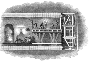
A tunnelling shield is a protective structure used during the excavation of large, man-made tunnels. When excavating through ground that is soft, liquid, or otherwise unstable, there is a risk to workers and the project itself from falling materials and/or a cave-in. A tunnelling shield serves as a temporary support structure. It is in place for the usually short time from when the tunnel section is excavated until it can be lined with a permanent support structure. The permanent structure may be made up of, depending on the period, bricks, concrete, cast iron, or steel. Although modern shields are commonly cylindrical, the first "shield", designed by Marc Isambard Brunel, was actually a large, rectangular, scaffold-like iron structure with three levels and twelve sections per level and a solid weight-bearing top — see picture to the right. The structure nevertheless protected the men from cave-ins as they laboured within it, digging the tunnel out in front of themselves.
History
The first successful rectangular tunnelling shield was developed by Marc Isambard Brunel and patented by him and Lord Cochrane in January 1818. Marc Brunel and his son Isambard Kingdom Brunel used it to excavate the Thames Tunnel beginning in 1825 (though the tunnel was not opened until 1843).[1] Brunel is said to have been inspired in his design by the shell of the shipworm Teredo navalis, a mollusc whose efficiency at boring through submerged timber he observed while working in a shipyard.[1] The shield was built by Maudslay, Sons & Field of Lambeth, London, who also built the steam pumps for de-watering the tunnel.
Brunel's original design was substantially improved by James Henry Greathead in the course of the construction of the Tower Subway under the River Thames in central London in 1870. Whilst many attribute the design shift from rectangular to cylindrical to Barlow, Greathead was the first to ever build a patented cylindrical tunnelling shield. Probably the most crucial innovation of Peter W. Barlow's 1864 patented design was that it had a circular cross-section (unlike Brunel's, which was of rectangular construction), which at once made it theoretically simpler in construction and better able to support the weight of the surrounding soil; theoretically because Barlow never built his patented idea whereas Greathead did. The shield was 7 ft 3in (2.2 metres) in diameter.
The 1868 Barlow design was further improved and given a provisional patent in 1868 but James Henry Greathead independently came up with his own designs and two successive patents for different shield designs of which one was for the construction of the City and South London Railway (today part of London Underground's Northern line) in 1884, with tunnels 10 ft 2in (3.1 metres) in diameter.
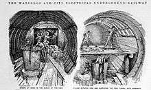
His system was also used in the driving of the 12-foot-1 3⁄4-inch (3.7 metres) diameter running tunnels for the Waterloo & City Railway which opened in 1898; Barlow was joint Engineer [with Greathead? ] to the project until his death. The station tunnels at the City station (now known as Bank) were the largest diameter tunnelling shields in the world at the time, measuring 23 feet (7 metres).
To this day, most tunnelling shields are still loosely based on Greathead Shields.[2] Greathead patented three shield designs which are documented in the article in his name. Additionally, Greathead invented the concept of sprayed concrete grout to stabilise earthworks with shot concrete. This is evidenced by his patent of his second tunnelling shield design with a gritting pan that hydraulically injected reinforcing grout between the constructed lining and the tunnel wall.
An original Greathead Shield used in the excavation of the deep London Underground lines remains in place in disused tunnels beneath Moorgate station.[3]
Manual shield tunnelling
In early shield tunnelling, the shield functioned as a way to protect labourers who performed the digging and moved the shield forward, progressively replacing it with pre-built sections of tunnel wall. The early deep tunnels for the London Underground were built in this way. The shield divided the workface into overlapping portions that each worker could excavate.
Modern tunnel boring machines
A tunnel boring machine (TBM) consists of a shield (a large metal cylinder) and trailing support mechanisms.
A rotating cutting wheel is located at the front end of the shield. Behind the cutting wheel there is a chamber where the excavated soil is either mixed with slurry (so-called slurry TBM) or left as-is (earth pressure balance or EPB shield), depending on the type of the TBM. The choice of TBM type depends on the soil conditions. Systems are also present for removal of the soil (or the soil mixed with slurry).
Behind the chamber there is a set of hydraulic jacks supported by the finished part of the tunnel which are used to push the TBM forward. Once a certain distance has been excavated (roughly 1.5–2 meters), a new tunnel ring is built using the erector. The erector is a rotating system which picks up precast concrete segments and places them in the desired position.
Several support mechanisms can be found behind the shield, inside the finished part of the tunnel, which are part of the TBM: dirt removal, slurry pipelines if applicable, control rooms, rails for transport of the precast segments, etc.
Lining
The tunnel lining is the wall of the tunnel. It usually consists of precast concrete segments which form rings. Cast iron linings were traditionally used in the London Underground tunnels, while steel liners were sometimes used elsewhere. The concept of using precast moulded lining sections is not new and was first patented by James Henry Greathead
Shields in Japan
In Japan there are several innovative approaches to shield tunnelling, e.g. the Double-O-Tube or DOT-tunnel. This tunnel looks like two overlapping circles. There are also shields with computerized arms which can be used to dig a tunnel in virtually any shape.[4]
References
- 1 2 Becket, Derrick (1980). Brunel's Britain. Newton Abbot: David & Charles. ISBN 0-7153-7973-9. Chapter 10: "Tunnels".
- ↑ John C Gillham, The Waterloo & City Railway, The Oakwood Press, Usk, 2001, ISBN 0 85361 525 X
- ↑ "The Tube: An Underground History, broadcast 16 May 2013". bbc.co.uk. 2013. Retrieved 17 May 2013.
- ↑ "Special Shield Tunnels". Nippon Civic Consulting Engineers Co., Ltd. Retrieved 2011-07-24.
Further reading
A full description of the tunnelling works for the Waterloo & City Railway, including the Greathead shield work and the compressed air arrangements, is given in the periodical The Engineer for 26 July 1895 and 2 August 1895; these can be seen online at Graces Guide .
External links
- Herrenknecht, TBM manufacturer
- Kidoh Construction, Micro-tunneling specialist in Japan
- A picture of manual tunneling using a Greathead shield