Texas Instruments SN76477

SN76477 "complex sound generator" is a sound chip produced by Texas Instruments (TI). The chip came to market in 1978,[1] and TI production of the part ceased some time ago. More recently, a 100% compatible version, identified as ICS76477, has been listed as 'in stock' by at least one US-based component stockist.[2] The chip is typically used as a sound effects generator in arcade games and toys and for hobby projects. The use of the SN76477 in a musical context is limited by the fact that it was difficult to electronically control the pitch of the produced sound.[3]
Overview
The following quotation summarizes its facilities:
[T]he SN76477 generates complex audio signal waveforms by combining the outputs of a low frequency oscillator, variable frequency (voltage controlled) oscillator, and noise source, modulating the resulting composite signal with a selected envelope and, finally, adjusting the signal's attack and decay periods. At each stage, the process can be controlled at the programming inputs of the signal modification and generation circuits, using control voltages, logic levels, or different resistor and capacitor values.
There were two different sizes of the SN76477 available. The SN76477N was in a standard 0.6 in (15.24 mm) width dual in-line package (DIP). The SN76477NF was in a less common 0.4 inch (10.16 mm) width DIP.

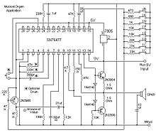
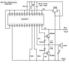
The text below is intended to explain the use of the 76477 in the demo circuit shown at the bottom right.
- SW1 (rotary) is a five position rotary switch that selects which capacitor controls the one-shot circuit that sets the envelope timing.
- SW24 (toggle or momentary) is the one-shot trigger switch, closed position is active.
- R1 a one megohm linear potentiometer sets the actual one-shot timing (in series with fixed 27K resistor R2)within the range selected by rotary switch SW1.
- SW2 (rotary) is a five position rotary switch which selects which capacitor sets the range for the low frequency oscillator (SLF oscillator in future references).
- SW3 (toggle or momentary) is the switch used to turn the low frequency oscillator on or off.
- R3 a one meagohm linear potentiometer (in series with 27K fixed resistor R4) sets the actual frequency for the SLF oscillator.
- SW4 (toggle or momentary) is the switch that takes control of the VCO duty cycle(called pitch control). If the switch is off the VCO operates at 50% duty cycle by default.
- R6 a 50K ohm linear potentiometer is used (in series with a 50K ohm fixed resistor R5) form a voltage divider used to set the VCO duty cycle, the on time vs off time of the waveform (note that most variable inputs to this chip are looking for a resistance, this input looks for a voltage). The source voltage for this voltage divider (R5 & R6) is the five volt buss.
- SW6 (rotary) is a four position rotary switch which selects which one of three resistors (or no resistor) sets the range of frequency for the VCO.
- SW5 (toggle or momentary) is the switch that turns the VCO on or off.
- R8 is a one megohm linear potentiometer (in series with 27K fixed resistor R7) which sets the actual frequency of the VCO (within the range selected by SW6).
- SW7 (rotary) is a six position rotary switch which selects which of six capacitors also sets the VCO frequency range.
- SW8(toggle or momentary) is the switch that selects either an internal voltage control or an external voltage control for the VCO (if set to the external input with no input connected then there is no extra VCO control).
- R12 a 50K ohm linear potentiometer is used (in series with a 50K ohm fixed resistor R13) form a voltage divider used to set an internal voltage to mimic the action of an external VCO input. The source for this voltage divider is the five volt buss.
- SW9 (rotary) is a five position rotary switch which selects which resistor sets the audio output level (called out as amplitude control resistor on the chip pinout)..
- SW10 (toggle or momentary) is the switch that enables attack timing. If this switch is open, there is no attack slope (tone is instant on). If this switch is closed the attack slope is set by R24 (within the range selected by SW11).
- R24 is a one megohm linear potentiometer (in series with 27K fixed resistor R23) which sets the actual attack timing (within the range selected by SW11).
- SW11 (rotary) is a six position rotary switch which selects which of six capacitors also sets the limits of the timing of the attack decay envelope generator.
- SW12 (toggle or momentary) is the switch that enables delay timing. . If this switch is open, there is no decay delay slope (tone is instant off). If this switch is closed the decay slope is set by R24 (within the range selected by SW11).
- SW13 (rotary) is a four position rotary switch which selects which one of four capacitors affects the noise filter.
- SW14 (toggle or momentary) is the switch that enables the noise filter.
- R26 is a one megohm linear potentiometer (in series with 27K fixed resistor R25) which sets the actual response of the noise filter timing (within the range selected by SW13.
- SW15 and SW16 (toggle and momentary in parallel) these two switches are tied to pin five of the 76477 sound generator. Most demonstration circuits I have seen show these two switches in parallel from pin five to ground. Pin five is the ‘system enable’ pin for the 76477. if pin five is open, the sound generator is off. If pin five is connected to ground, the sound generator is running. I included both switches for that reason.
- SW17 (toggle or momentary) is the switch that enables the internal noise generator clock. If this switch is closed then the noise generator operates on its internal clock.
- R29 A fixed resistor, value 47K. This resistor is in series with SW17 and is the current reference for the internal noise generator clock. In the 76477 spec sheet this is called out as 47K. I am sure that you could ;tweak; this value somewhat but straying too far from 47K might make the internal noise clock unstable. If you want to control the clock frequency then the next Item, ‘J1' would be a better choice.
- J1 External noise clock input. If this input is used SW17 should be open (or off). Waveform can be most any wave shape and most any frequency from a few hertz to about 2mhz and can range from a half a volt to a maximum of five volts. Note: some very strange tones can be produced with a rather low frequency input to this jack.
- SW18 and SW19 (toggle or momentary) are switches that together control the logic for the envelope generator. If both switches are open then the VCO only is selected. If SW18 is closed and * SW19 is open the envelope generator is controlled by the one shot generator. If SW18 is open and SW19 is closed the mixer only is selected. If both SW18 and SW19 are closed the VCO is selected with alternating polarity.
- SW20 – SW21 and SW22 (toggle or momentary) are switches that together control the logic for the mixer. The logic is as follows SW20, 21 and 22 open selects the VCO, SW20 on and SW21 and 22 open selects the super low frequency oscillator, with noise filter. SW21 on and SW20 and SW22 off selects the noise generator output only, SW20 and 21 on and SW22 off selects the SLF oscillator and the VCO. SW20 and 21 off and SW22 on selects the SLF oscillator only. SW20 and 22 on and SW21 off selects the SLF and the VCO and the noise generator. SW20 off and SW21 and 22 on selects the VCO and the noise filter. SW20 and 21 and 22 on inhibits the mixer (audio off).
- SW23 (toggle or momentary) is the switch that selects what voltage input the VCO will follow. If SW23 is open the VCO will be controlled by the SLF oscillator. If SW23 is closed then the VCO will be modulated by the voltage input to pin16 (which in this circuit can be selected by SW8 to be the level set by R12 or an external voltage input to J2).
- J2 External VCO input voltage (selected or disabled by SW8. Can be most any wave shape and most any frequency from a few hertz to about several kilohertz and can range from a half a volt to a maximum of five volts.

Uses
Uses of the SN76477 include the following devices:
- Arcade games:
- Space Invaders[5]
- Stratovox
- Vanguard
- Sheriff/Bandido
- Educational toys:
- Gakken EX-System synthesiser
- Electronic musical instruments:
- Home computers:
See also
- Texas Instruments SN76488 - sound chip with internal audio amplifier.
- Texas Instruments SN76489 - sound chip with 3x square wave and 1x white noise generator


References
- ↑ Type SN76477 Complex Sound Generator Archived 2009-10-07 at the Wayback Machine. – Texas Instruments Bulletin No. DL-S 12612, July 1978, (The datasheet)
- ↑ BG-Micro lists ICS76477 Sound Generator. Archived 2010-02-13 at the Wayback Machine.
- ↑ SN-Voice: discussion of the SN Voice synthesiser. Archived 2008-06-29 at the Wayback Machine.
- ↑ Solid State, Popular Electronics Magazine, October 1978.
- ↑ 8080a Simulation: Space Invaders – a report on writing an emulator for Space Invaders.
External links
- www.popsci.com article: Complex Sound Generator IC is Back 12.12.2008
- SN76477 data sheet
- A collection of articles on the chip
- 76477 chips available on eBay in wide and narrow format
- Reverse engineering the 76477 "Space Invaders" sound effect chip from die photos