Subtractor
In electronics, a subtractor can be designed using the same approach as that of an adder. The binary subtraction process is summarized below. As with an adder, in the general case of calculations on multi-bit numbers, three bits are involved in performing the subtraction for each bit of the difference: the minuend ( ), subtrahend ( ), and a borrow in from the previous (less significant) bit order position ( ). The outputs are the difference bit ( ) and borrow bit . The subtractor is best understood by considering that the subtrahend and both borrow bits have negative weights, whereas the X and D bits are positive. The operation performed by the subtractor is to rewrite (which can take the values -2, -1, 0, or 1) as the sum .


Subtractors are usually implemented within a binary adder for only a small cost when using the standard two's complement notation, by providing an addition/subtraction selector to the carry-in and to invert the second operand.
- (definition of two's complement notation)


Half subtractor
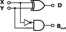
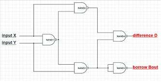
The half subtractor is a combinational circuit which is used to perform subtraction of two bits. It has two inputs, the minuend and subtrahend and two outputs the difference and borrow out . The borrow out signal is set when the subtractor needs to borrow from the next digit in a multi-digit subtraction. That is, when . Since and are bits, if and only if and . An important point worth mentioning is that the half subtractor diagram aside implements and not since on the diagram is given by


- .

This is an important distinction to make since subtraction itself is not commutative, but the difference bit is calculated using an XOR gate which is commutative.
The truth table for the half subtractor is:
| Inputs | Outputs | ||
|---|---|---|---|
| X | Y | D | Bout |
| 0 | 0 | 0 | 0 |
| 0 | 1 | 1 | 1 |
| 1 | 0 | 1 | 0 |
| 1 | 1 | 0 | 0 |
Using the table above and a Karnaugh map, we find the following logic equations for and :
- .

Consequently, a simplified half-subtract circuit, advantageously avoiding crossed traces in particular as well as a negate gate is:
      X ── XOR ─┬─────── |X-Y|,  is 0 if X equals Y, 1 otherwise
         ┌──┘   └──┐
      Y ─┴─────── AND ── borrow, is 1 if Y > X, 0 otherwise
where lines to the right are outputs and others (from the top, bottom or left) are inputs.
Full subtractor
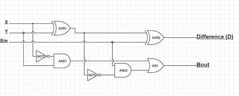
The full subtractor is a combinational circuit which is used to perform subtraction of three input bits: the minuend , subtrahend , and borrow in . The full subtractor generates two output bits: the difference and borrow out . is set when the previous digit is borrowed from . Thus, is also subtracted from as well as the subtrahend . Or in symbols: . Like the half subtractor, the full subtractor generates a borrow out when it needs to borrow from the next digit. Since we are subtracting by and , a borrow out needs to be generated when . When a borrow out is generated, 2 is added in the current digit. (This is similar to the subtraction algorithm in decimal. Instead of adding 2, we add 10 when we borrow.) Therefore, .


The truth table for the full subtractor is:
| Inputs | Outputs | |||
|---|---|---|---|---|
| X | Y | Bin | D | Bout |
| 0 | 0 | 0 | 0 | 0 |
| 0 | 0 | 1 | 1 | 1 |
| 0 | 1 | 0 | 1 | 1 |
| 0 | 1 | 1 | 0 | 1 |
| 1 | 0 | 0 | 1 | 0 |
| 1 | 0 | 1 | 0 | 0 |
| 1 | 1 | 0 | 0 | 0 |
| 1 | 1 | 1 | 1 | 1 |
Therefore the equation is D=X⊕Y⊕Bin and Bout=X'Bin+X'Y+YBin
See also
References
- Foundations Of Digital Electronics by Elijah Mwangi