Rock mass rating
The Rock Mass Rating (RMR) System is a geomechanical classification system for rocks, developed by Z. T. Bieniawski between 1972 and 1973.[1] It combines the most significant geologic parameters of influence and represents them with one overall comprehensive index of rock mass quality, which is used for the design and construction of excavations in rock, such as tunnels, mines, slopes and foundations.
Definition
The following six parameters are used to classify a rock mass using the RMR system
- Uniaxial compressive strength of rock material
- Rock quality designation (RQD)
- Spacing of discontinuities
- Condition of discontinuities.
- Groundwater conditions
- Orientation of discontinuities
Each of the six parameters is assigned a value corresponding to the characteristics of the rock. These values are derived from field surveys and laboratory tests. The sum of the six parameters is the "RMR value", which lies between 0 and 100.
Classification table
Below is the classification table for the RMR system.
| RMR | Rock quality |
|---|---|
| 0 - 20 | Very Poor |
| 21 - 40 | Poor |
| 41 - 60 | Fair |
| 61 - 80 | Good |
| 81 - 100 | Very good |
Procedures
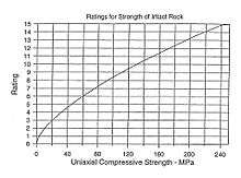
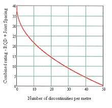
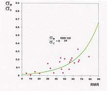
The details for calculating RMR are given elsewhere by edumine and provide a series of tables for RMR determination while the latest charts for the same purpose are given in the references and further reading. In particular, the charts enclosed here for the RMR parameters intact rock strength and the combined parameters RQD and discontinuity spacing (represented by the number of discontinuities per meter), show the advantage of using the charts for better accuracy, rather than relying on the tables which show the average ratings for the ranges of each RMR parameter.
Applications
Rock Mass Rating RMR has found wide applications in various types of engineering projects such as tunnels, slopes, foundations, and mines. It is also adaptable for knowledge-based expert systems. Engineers informally classify rock structure into two general classifications: continuous homogenous isotropic linear elastic (what most geotechnical engineers would like to see) and discontinuous inhomogenous anisotropic non-elastic (what most in-situ rock masses actually are). A rock mass rating system provides a method of incorporating some of the complex mechanics of actual rocks into engineering design.
Moreover, the system was the first to enable estimation of rock mass properties, such as the modulus of deformation, in addition to providing tunnel support guidelines and the stand-up time of underground excavations.[2]
Recently, after over 40 years of use, renewed attention was paid to the RMR System because of its applications to the assessment of rock mass excavability (RME) and, especially, its direct correlation with the specific energy of excavation (SEE) for TBMs used effectively to detect changes in tunneling conditions, in real time, thus serving as a warning of adverse conditions as construction proceeds.[3]
Rock Mass Rating presents some difficulties when applied to rock slopes, since the parameter that take into account the influence of the discotinuities orientation is introduced in detail for dam foundations and tunnels but not for slopes[4]. To address this issue, Romana[5] defined Slope Mass Rating scheme that is based on the original Bieniawski's parameters but including a rigorous definition of the parameters considering the effect of the orientation of discontinuities.
Specific Output Charts for Tunnel Design
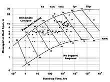
For convenience in tunnel design, three charts are included which are commonly used to estimate these essential rock mass properties: Stand up time, Rock mass deformability modulus Em and Rock mass strength. See References.
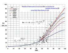
In the second chart, an improved relationship for the range of RMR greater than 56 is given. This reflects the idea that, at high RMR, deformations will be dominated by intact modulus, whereas at lower RMR weathering and joint infilling will largely control deformation. This approach has the advantage that modulus values are NOT overestimated at the higher range nor underestimated or overestimated at the lower range. This is more realistic than relying on one sigmoidal equation.
A note of caution: A number of sigmoidal equations have been proposed that give rock mass modulus as a function of intact modulus and a rock mass rating. These equations may give a good estimate of modulus given the correct input data, however it is difficult to obtain reliable intact strength or intact modulus values from laboratory tests on samples from highly disturbed rock masses. Because of this limitation, something that is commonly done in practice is to base intact modulus values on test results done on good samples of intact rock from locations with competent rock, using either laboratory measurements of intact modulus or on an assumed ratio between intact strength and modulus for a particular rock type. This ignores the possibility that the material in zones with poor rock will often be highly weathered, and it ignores the possibility that even without weathering a zone of poor rock may represent rock which simply has a lower intact strength, and that is why it became disturbed while zones of stronger rock on the same project did not.
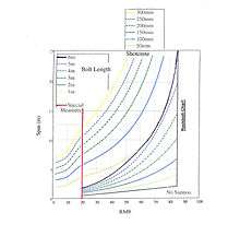
A note on tunnel support guidelines: The tunnel support guidelines based on RMR were provided originally in the form of a table giving support recommendations for a tunnel span/diameter of 10 meters. In view of the improving technology for rock bolting, shotcrete and steel ribs, it was left to tunnel designers to modify these guidelines for other tunnel sizes, which served its purpose well. Today, after 40 years of use, it has become apparent that it would be convenient for practical tunnel designers to have charts for the selection of rock support as a function of both tunnel size and rock mass quality. This is depicted in the chart below (see Lawson 2013).
See also
References
- ↑ Bieniawski, Z. T. (1989). Engineering rock mass classifications : a complete manual for engineers and geologists in mining, civil, and petroleum engineering. Wiley-Interscience. pp. 40–47. ISBN 0-471-60172-1.
- ↑ Bieniawski, Z. T. (1978). "Determining rock mass deformability". Int. J. Rock Mech. Min.Sci: v. 15, 335–343.
- ↑ Celada; et al. (2012). "Specific energy of excavation in detecting tunnelling conditions ahead of TBMs". Tunnels & Tunneling: v. February, 65-68.
- ↑ https://link.springer.com/article/10.1007%2Fs10913-008-0005-2
- ↑ Romana M. (1985). New adjustment ratings for application of Bieniawski classification to slopes. Proc. Int. Symp. on the Role of Rock Mechanics: 49-53.
- ASTM (1988). "Standard Guide for using the Rock Mass Rating (RMR) System (Geomechanics Classification) in Engineering Practices." American Society for Testing and Materials, Book of Standards D5878-08, v.04.09, Philadelphia, PA.
Further reading
- Lowson, A. (2013). "Critical assessment of RMR based tunnel design practices". Proc. RETC. Washington DC: Society of Mining Engineers. pp. 180-198.
- Pantelidis L. (2009) "Rock slope stability assessment through rock mass classification systems" Int. J.Rock Mech. Min.Sci., 46(2):315–325.