Radio Data System
.svg.png)
Radio Data System (RDS) is a communications protocol standard for embedding small amounts of digital information in conventional FM radio broadcasts. RDS standardizes several types of information transmitted, including time, station identification and program information.
The standard began as a project of the European Broadcasting Union (EBU), but has since become an international standard of the International Electrotechnical Commission (IEC).
Radio Broadcast Data System (RBDS) is the official name used for the U.S. version of RDS.[1] The two standards are only slightly different.
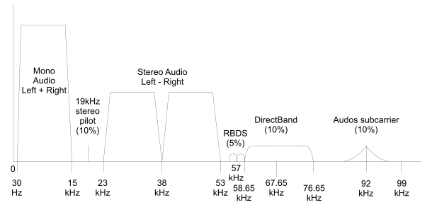
Both carry data at 1,187.5 bits per second on a 57 kHz subcarrier, so there are exactly 48 cycles of subcarrier during every data bit. The RBDS/RDS subcarrier was set to the third harmonic of the 19 kHz FM stereo pilot tone to minimize interference and intermodulation between the data signal, the stereo pilot and the 38 kHz DSB-SC stereo difference signal. (The stereo difference signal extends up to 38 kHz + 15 kHz = 53 kHz, leaving 4 kHz for the lower sideband of the RDS signal.)
The data is sent with error correction. RDS defines many features including how private (in-house) or other undefined features can be "packaged" in unused program groups.
Development
RDS was inspired by the development of the Autofahrer-Rundfunk-Informationssystem (ARI) in Germany by the Institut für Rundfunktechnik (IRT) and the radio manufacturer Blaupunkt.[2] ARI used a 57-kHz subcarrier to indicate the presence of traffic information in an FM radio broadcast.[3]
The EBU Technical Committee launched a project at its 1974 Paris meeting to develop a technology with similar purposes to ARI, but which was more flexible and which would enable automated retuning of a receiver where a broadcast network transmitted the same radio programme on a number of different frequencies. The modulation system was based on that used in a Swedish paging system and the baseband coding was a new design, mainly developed by the British Broadcasting Corporation (BBC) and the IRT. The EBU issued the first RDS specification in 1984.[2]
Enhancements to the alternative frequencies functionality were added to the standard and it was subsequently published as a European Committee for Electrotechnical Standardization (CENELEC) standard in 1990.[2]
In 1992 the U.S. National Radio Systems Committee issued the North American version of the RDS standard, called the Radio Broadcast Data System. The CENELEC standard was updated in 1992 with the addition of Traffic Message Channel and in 1998 with Open Data Applications[2] and, in 2000, RDS was published worldwide as IEC standard 62106.[4]
RDS 2.0
The RDS-Forum (Geneva / CH) decided at its annual meeting (8-9 June 2015) in Glion/Montreux to bring the new standard RDS2 on the way. The standard will be created in close collaboration with U.S. colleagues from NRSC RBDS-Subcommittee and should offer a unified platform for FM broadcasting and data services worldwide.
- Key features are
- Seamless support for frequencies from 64 MHz to 108 MHz (AF, EON)
- New character coding: UTF-8 (old EBU Charset remains for compatibility mode for the old 0A/2A Groups).
- New ODA handling, "B" groups are assigned as signalling group to the “A” groups.
- Long PS-Name, up to 32 byte with UTF-8 character set. (Indian, Chinese, Arabic, and more)
- RadioText (eRT) 128 byte long with UTF-8
- Increased capacity from 11.4 up to 57 "A"-groups per second. (2,109 bit/s. net capacity with the single modulation-type multiple subcarriers (SMMS) technology)
- Graphical RadioText – supports HTML/CSS templates (for smartphones, car radios, computers/tablets)
- Supports return channel over gRT if the receiver has IP or SMS capability.
- Broadcaster's graphical logo – a maximum 4 kilobyte picture (JPEG, PNG, or GIF)
- Hybrid Radio feature (partly based on Radio France development)
Content and implementation
The following information fields are normally contained in the RDS data:
- AF (alternative frequencies list)
- This provides the receiver with a list of frequencies that allows a receiver to re-tune to a different frequency providing the same station when the first signal becomes too weak (e.g., when moving out of range). Before performing the switch, a radio will check for a matching PI code to ensure the AF is the same station. This is often used in car stereo systems, allowing the head unit to automatically tune into the stronger signal on the move, optionally with the same regional code (so that, in the case of national broadcasting stations, the user can keep listening to the original radio program).
- CT (clock time and date)
- Can synchronize a clock in the receiver or the main clock in a car. Due to transmission vagaries, CT can only be accurate to within 100 ms of UTC. CT is not usually transmitted if a broadcaster has no way to regularly synchronise the clock within the RDS encoder.
- EON (enhanced other networks information)
- Informs the receiver about other networks or stations, linked to the one being listened to, for dynamically changing data such as the TA flag turning on for a particular station of the network in a particular moment due to a traffic programme being broadcast, and automatically and temporarily tune into that station.
- PI (programme identification)
- This is the unique 4 character hexadecimal code that identifies the station. Every station in a country should use a unique 3 character code with the correct country prefix character. In the US, PI is determined by applying a formula to the station's call sign. The US NRSC is seeking to add an ancillary traffic type to lessen confusion. The PI code is the most important RDS parameter and the most frequently transmitted within the RDS data structure. The RDS standard for non US use defines country codes for all countries so that no where with common borders has the same code. This removes the need to coordinate codes between different countries. Any transmission that carries the same code is considered by receivers to be the same and can be switched to as an alternative frequency to improve reception (even if it is not specifically listed as an alternative frequency).
- PS (programme service name)
- This is simply an eight-character static display that represents the call letters or station identity name. Most RDS capable receivers display this information and, if the station is stored in the receiver's presets, will cache this information with the frequency and other details associated with that preset. In some countries, stations use the PS to dynamically send other information. This is prohibited in some countries and was not its intended use within the RDS system.
- PTY (programme type)
- This coding of up to 31 pre-defined programme types (e.g., in Europe: PTY1 News, PTY6 Drama, PTY11 Rock music) allows users to find similar programming by genre. PTY31 seems to be reserved for emergency announcements in the event of natural disasters or other major calamities.
- REG (regional)
- This is mainly used in countries where national broadcasters run "region-specific" programming such as regional opt-outs on some of their transmitters. This functionality allows the user to "lock-down" the set to their current region or let the radio tune into other region-specific programming as they move into the other region.
_on_95.9_KFSH_La_Mirada.jpg) An example of RT RDS on Los Angeles' KFSH - FM
An example of RT RDS on Los Angeles' KFSH - FM - RT (radio text)
- This function allows a radio station to transmit a 64-character free-form text that can be either static (such as station slogans) or in sync with the programming (such as the title and artist of the currently playing song).
- RT+ (radio text plus)
- An enhancement of the original RT which allows Artist, Title and some other metadata to be sent to receivers.
- TA, TP (traffic announcement, traffic programme)
- The receiver can often be set to pay, taking advantage of the EON linkage if it's available, special attention to this flag and, for example, pause a CD or retune to receive a traffic bulletin. The TP flag is used to allow the user to find only those stations that regularly broadcast traffic bulletins whereas the TA flag is used to signal an actual traffic bulletin in progress, with radio units perhaps performing other actions such as pausing a CD/MP3 (so the radio can be heard) or raising the volume during the traffic bulletin.
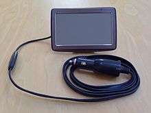
- TMC (traffic message channel)
- Digitally encoded traffic information. Not all RDS equipment supports this, but it is often available for automotive navigation systems. In many countries only encrypted traffic data is broadcast, and so an appropriate decoder, possibly tied to a subscription service, is required to use the traffic data. The subscription is often paid by the vehicle manufacturer and is therefore transparent to the user.
- US NRSC FM Translator Announcements: The National Radio Systems Committee has introduced a unique Radio Data System Program Identification code for US FM translators. One type of metadata transmitted by RDS subcarrier is the PI code, which is used by the receiver to uniquely identify the audio program being broadcast by the FM station. In the U.S., the PI code has historically been derived from a radio station’s call sign, which can become complicated when used in conjunction with FM translators. A new algorithm just for FM translators has been created that assigns a unique PI code to each FM translator. This algorithm has been implemented using a web-based tool and a list of all known PI codes for all FM translators in the US.
RDS support
As far as implementation is concerned, most car stereos will support at least AF, EON, REG, PS and TA/TP.
- More expensive car stereos will offer TMC, RT and / or PTY, perhaps with "NEWS" override.
- Home systems, especially hi-fi receivers, will mainly support functions like PS, RT and PTY.
There are a growing number of RDS implementations in portable audio and navigation devices thanks to lower-priced, small-footprint solutions.
RDS compatibility
The RDS sub-carrier at 57 kHz occupies ±2 kHz of the composite spectrum which in theory keeps it above the upper cutoff of the stereo subcarrier at 53 kHz. However the 53 kHz cutoff is entirely dependent on the performance of the 15 kHz low pass filters used before the stereo encoder. In older equipment, these filters were only designed to protect the 19 kHz pilot and sometimes did not provide sufficient protection to the RDS subcarrier when a significant amount of stereo information was present. In this situation, stereo enhancement devices combined with aggressive audio processing could render the RDS subcarrier unreceivable.
Composite clipping systems may also degrade the RDS sub-carrier because of the harmonics created by the clipping. More modern composite clippers include filtering to protect the RDS subcarrier.
The RDS subcarrier typically uses 2–4 kHz of carrier deviation. Therefore, the deviation available for the program material is reduced by this amount, assuming the usual 75 kHz deviation limit is not exceeded.
Program types
The following table lists the RDS and RBDS program type (PTY) codes and their meanings:
PTY code RDS program type (EU) RBDS program type (North America) 0 No programme type or undefined No program type or undefined 1 News News 2 Current affairs Information 3 Information Sports 4 Sport Talk 5 Education Rock 6 Drama Classic rock 7 Culture Adult hits 8 Science Soft rock 9 Varied Top 40 10 Pop music Country 11 Rock music Oldies 12 Easy listening Soft 13 Light classical Nostalgia 14 Serious classical Jazz 15 Other music Classical 16 Weather Rhythm and blues 17 Finance Soft rhythm and blues 18 Children’s programmes Language 19 Social affairs Religious music 20 Religion Religious talk 21 Phone-in Personality 22 Travel Public 23 Leisure College 24 Jazz music Spanish Talk 25 Country music Spanish Music 26 National music Hip Hop 27 Oldies music Unassigned 28 Folk music Unassigned 29 Documentary Weather 30 Alarm test Emergency test 31 Alarm Emergency
The later RBDS standard made no attempt to match the original RDS plan, therefore several identical radio formats were given different numbers, including jazz, weather, sports, and rock. Other similar formats such as varied/college and phone-in/talk are also mismatched. This is mainly a problem for Americans taking portable radios out of their country.
RDS Technical Specification
The RDS standard as specified in `EUROPEAN STANDARD EN50067` [6] is separated into these sections according to the OSI model (Excluding network and transport layer, since this is a broadcasting standard).
- Data Channel (Physical Layer)
- Baseband Coding (Data-Link Layer)
- Message Format (Session And Presentation Layer)
Data Channel (Physical Layer)
The physical layer in the standard describes how the bitstream is retrieved from the radio signal. The RDS hardware first demodulates the 57 kHz RDS subcarrier signal to extract a Biphase encoded signal which contains both the bitrate clock and the differentially encoded bitstream. This allows for retrieving the RDS bitstream via a differential decoder, which requires a synchronised clock and a differentially encoded bit-stream.
Baseband Coding (Data-Link Layer)
The data-link layer describes the baseband coding of which the largest element in the structure is called a "group" sized 104 bits wide. Within each group are 4 blocks sized 26bits wide. Each block contains a 16bit data word and a 10 bit checkword. In the case of the FM Tuner RDA5807M IC, it displays a group in separate 16bits blocks over four i2c registers. All group is sent most significant byte first, with no gap between groups or blocks.
| Structure Type | most significant bit sent first | least significant bit received last | ||||||
|---|---|---|---|---|---|---|---|---|
| Group | Group : 104 bits | |||||||
| Version | Block 1 : 26bits | Block 2 : 26bits | Block 3 : 26bits | Block 4 : 26bits | ||||
| Block Internal | Payload : 16 bits | Check + Offset A : 10 bits | Payload : 16 bits | Check + Offset B : 10 bits | Payload : 16 bits | Check + Offset C or C' : 10 bits | Payload : 16 bits | Check + Offset D : 10 bits |
| Note: | Offset C = Version A
Offset C' = Version B |
|||||||
Synchronisation of the baseband coding structure from the RDS bitstream
The identification of a RDS message blocks and groups is done via a 10-bit offset table containing offset word: A, B, C, C' , and D (in RBDS this also includes "E").
Message Format (Session And Presentation Layer)
A RDS message group consist of two versions of the group structure, designated in the standard as type A, and type B.
Shared Structure
Within Block 1 and Block 2 are structures that will always be present in both group versions, for fast and responsive identifications. First block of every group, will always be the program identification code. The second block dedicates the first 4 bits for Application/Group Type.
| Block 1 | Block 2 | |||||
| Block Meaning | Program Identification Code | GTYPE | B0 | TP | PTY | ???? |
| bit notation per block | b15 ----> b0 | b15 -> b12 | b11 | b10 | b9 -> b5 | b4 -> b0 |
| Fixed Meaning Per Group? | Yes | Yes | Yes | Yes | Yes | No |
Meaning of Block 2 Bits
- GTYPE: Group Type
- B0: If B0=0 then Message Group Type A else Type B
- TP: Traffic Program. Indicates if this is a traffic alert radio program.
- PTY: Program Type
- ????: Rest of the bits are group type dependent
Message Version A
| Block 1 | Block 2 | Block 3 | Block 4 | |||||
| Block Meaning | Program Identification Code | Group Type | B0 | TP | PTY | APP | Group Specific Payload | Group Specific Payload |
| Block Payload Bit Value | XXXX XXXX XXXX XXXX | XXXX | 0 | X | XXXXX | XXXXX | XXXX XXXX XXXX XXXX | XXXX XXXX XXXX XXXX |
| Offset Value (Sync) | Offset A | Offset B | Offset C | Offset D | ||||
Message Version B
Block 3 is used for repeating program identification code.
| Block 1 | Block 2 | Block 3 | Block 4 | |||||
| Block Meaning | Program Identification Code | Group Type | B0 | TP | PTY | APP | Program Identification Code | Group Specific Payload |
| Payload Bit Value | XXXX XXXX XXXX XXXX | XXXX | 1 | X | XXXXX | XXXXX | XXXX XXXX XXXX XXXX | XXXX XXXX XXXX XXXX |
| Offset Value (Sync) | Offset A | Offset B | Offset C' | Offset D | ||||
Program Identification Code (PI Code)
This allows for quick identification of radio program type, based on country, coverage area, and program reference number. While the country code is specified by the standard, bit 11 to bit 0 is specified by each country local authorities.
| PI Code | Nibble 0 | Nibble 1 | Nibble 2 | Nibble 3 | ||||||||||||
| Meaning | Country Code | Program Area Coverage | Program Reference Number | |||||||||||||
| Bit Position | b15 | b12 | b11 | b8 | b7 | b4 | b3 | b0 | ||||||||
Group Type
This is a short list of the full group type. Each group type may have a secondary version available
| Group Type | Bit Value | Message Version A | Message Version B |
| 0 | 0000 | Basic Tuning and Switching Information Only | |
| 1 | 0001 | Program Item Number and Slow Labeling Code | Program Item Number |
| 2 | 0010 | Radio Text | |
| 3 | 0011 | Application Identification for Open Data Applications | Open Data Applications |
| 4 | 0101 | Clock Time and Date | Open Data Applications |
| etc... | etc... | ||
RDS Message Examples
These are non comprehensive examples that covers just the simple messages likes station name, radio text, and date time.
Group Type 0 - Version B - Station Name
| Version | Block 1 : 26bits | Block 2 : 26bits | Block 3 : 26bits | Block 4 : 26bits | |||||||||||||
| Block Internal | PI Code | Check + Offset A | GTYPE | B0 | TP | PTY | TA | M/S | DI | C1 | C0 | Check + Offset B | PI Code | Check + Offset C' | Character A | Character B | Check + Offset D |
| Bit Value | 16 bits | 0000 | 1 | X | XXXXX | X | X | X | X | X | 16 bits | 8 bits char | 8 bits char | ||||
As we have already described previous fields above, these dot points below show just the application specific fields.
- TA : Traffic Announcement
- M/S : Music/Speech
The station name and decoder identification code is sent progressively over 4 groups, where the offset is defined by bit C1 and C0.
| Character Segment | Station Name : | Decoder Identification Code : 4 bit | ||||||||||||
| C1 | C0 | Offset | 0 | 1 | 2 | 3 | 4 | 5 | 6 | 7 | 3 | 2 | 1 | 0 |
| 0 | 0 | 0 | A | B | DI | |||||||||
| 0 | 1 | 1 | A | B | DI | |||||||||
| 1 | 0 | 2 | A | B | DI | |||||||||
| 1 | 1 | 3 | A | B | DI | |||||||||
Group Type 2 - Radio Text
| RadioText Version A | Block 1 : 26bits | Block 2 : 26bits | Block 3 : 26bits | Block 4 : 26bits | ||||||||||||||
| Block Internal | PI Code | Check + Offset A | GTYPE | B0 | TP | PTY | A/B | C3 | C2 | C1 | C0 | Check + Offset B | Character A | Character B | Check + Offset C | Character C | Character D | Check + Offset D |
| Bit Value | 16 bits | 0010 | 0 | X | XXXXX | X | X | X | X | X | 8 bits char | 8 bits char | 8 bits char | 8 bits char | ||||
| RadioText Version B | Block 1 : 26bits | Block 2 : 26bits | Block 3 : 26bits | Block 4 : 26bits | |||||||||||||
| Block Internal | PI Code | Check + Offset A | GTYPE | B0 | TP | PTY | A/B | C3 | C2 | C1 | C0 | Check + Offset B | PI Code | Check + Offset C' | Character C | Character D | Check + Offset D |
| Bit Value | 16 bits | 0010 | 1 | X | XXXXX | X | X | X | X | X | 16 bits | 8 bits char | 8 bits char | ||||
As we have already described previous fields above, these dot points below show just the application specific fields.
- A/B : Text A/B flag is used to detect if a screen clear is requested.
- C3 to C0 : Is the text segment offset value
The station name and decoder identification code is sent progressively over 4 groups, where the offset is defined by bit C1 and C0.
| Text Segment | Version A | Version B | ||||||||||
| C3 | C2 | C1 | C0 | Offset | Char A | Char B | Char C | Char D | Char A | Char B | Char C | Char D |
| 0 | 0 | 0 | 0 | 0 | 1 | 2 | 3 | 4 | Version B Specifies
That This Field Is For Program Identification Code |
1 | 2 | |
| 0 | 0 | 0 | 1 | 1 | 5 | 6 | 7 | 8 | 3 | 4 | ||
| 0 | 0 | 1 | 0 | 2 | 9 | 10 | 11 | 12 | 5 | 6 | ||
| ... | ... | ... | ... | etc... | ... | ... | ... | ... | ... | ... | ||
| 1 | 1 | 1 | 1 | 15 | 61 | 62 | 63 | 64 | 31 | 32 | ||
Group Type 4 - Version A - Clock Time and Data
| Version | Block 1 : 26bits | Block 2 : 26bits | Block 3 : 26bits | Block 4 : 26bits | |||||||||||
| Block Internal | PI Code | Check + Offset A | GTYPE | B0 | TP | PTY | R | R | R | Time/Date Data | Check + Offset B | Time/Date Data | Check + Offset C' | Time/Date Data | Check + Offset D |
| Bit Value | 16 bits | 0100 | 0 | X | XXXXX | 2 bits | 16 bits | 16 bits | |||||||
When group type 4A is used, it shall be transmitted every minute according to EN 50067.
The clock time group is inserted so that the minute edge will occur within +/- 0.1 seconds of the end of the clock time group.
Time and date are packed as these:
| Time/Date Data | Half Block 2 Payload | Block 3 Payload | Block 4 Payload | |||||||||||||||||||||||||||||||||||||
| Payload Bit Pos | 7 | 6 | 5 | 4 | 3 | 2 | 1 | 0 | 15 | 14 | 13 | 12 | 11 | 10 | 9 | 8 | 7 | 6 | 5 | 4 | 3 | 2 | 1 | 0 | 15 | 14 | 13 | 12 | 11 | 10 | 9 | 8 | 7 | 6 | 5 | 4 | 3 | 2 | 1 | 0 |
| Field Bit Pos | etc... | Reserved | 16 | 15 | 14 | 13 | 12 | 11 | 10 | 9 | 8 | 7 | 6 | 5 | 4 | 3 | 2 | 1 | 0 | 4 | 3 | 2 | 1 | 0 | 5 | 4 | 3 | 2 | 1 | 0 | 0 | 4 | 3 | 2 | 1 | 0 | ||||
| Description | Reserved | Modified Julian Day Code | UTC Hours | UTC Minutes | LOS | Local Time Offset | ||||||||||||||||||||||||||||||||||
Note: The local time offset is expressed in multiples of half hours within the range -12h to +12h
- LOS : Local Offset Sign ( 0 = + , 1 = - )
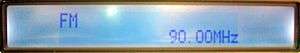
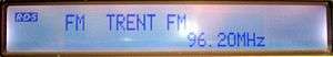
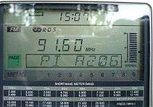
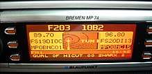
Example RDS usage
The following three images illustrate how RDS can be used on an FM radio station; the latter two were taken when the radio was tuned to Nottingham radio station Trent FM. All the images are of the display on the Sony XDR-S1 DAB/FM/MW/LW portable radio.

RDS chipsets
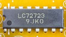
Companies such as ST Microelectronics, Silicon Labs in Austin, Texas and NXP Semiconductors (formerly Philips) offer single-chip solutions that are found in these devices.
See also
- High-level RDS APIs
- Advanced Multimedia Supplements (JSR-234) (in Java programming language)
- OpenMAX AL (in C programming language)
- Related technologies
- ALERT FM – RBDS emergency notification system
- HEARO – a defunct RBDS emergency notification system
- Data Radio Channel (DARC)
- DirectBand
- PSIP
- UECP – protocol (Universal Encoder Communication Protocol)[7]
- Related topics
- Digital radio
- Error correction
- FM broadcasting
- Internet radio device
- Modem
- Radio receiver
- Teletext ~6.5kbit/s data transmission over Analog TV channel
Notes
- ↑ "NRSC-4-B United States RBDS Standard" (PDF). National Radio Systems Committee.
- 1 2 3 4 "March 2009: RDS is now 25 – the complete history" (PDF). Geneva, Switzerland: The RDS Forum. 2009-03-27. p. 1. Retrieved 2011-06-15.
- ↑ EP 1432157
- ↑ "IEC Webstore Publication detail: IEC 62106 Ed. 1.0 English". Geneva, Switzerland: International Electrotechnical Commission. Retrieved 2009-05-18.
- ↑ "Traffic Receiver". TomTom. Retrieved 15 June 2014.
- ↑ EUROPEAN STANDARD EN50067 http://www.interactive-radio-system.com/docs/EN50067_RDS_Standard.pdf
- ↑ "Archived copy". Archived from the original on 2000-03-01. Retrieved 2016-02-08. EBU UECP Specification
References
- The Directory of European FM Broadcasting, European FM Handbook 2002–2003, 13th edition, published July 1, 2002, B5 format, ISBN 951-98733-1-7
- Dietmar Kopitz, Bev Marks, RDS: Radio Data System (Mobile Communications Library), ISBN 0-89006-744-9
- MSB VMA report,
- http://www.interactive-radio-system.com/docs/EN50067_RDS_Standard.pdf
External links
- FARWAY IRFC, TV and Radio Transmission , Radio Data System Encoders
- Specification of the RDS standard, available via the RDS Forum
- "NRSC-4 National Radio Systems Committee United States RBDS Standard – Specification of the radio broadcast data system (RBDS)"
- The RDS Forum is the professional association of the users of the Radio Data System broadcast technology
- xRDS "Extending the RDS data transmission capacity"
- RDSList.com
- GR-RDS on Github – A GNU Radio-based open source implementation of an RDS receiver and transmitter
- Decoding RDS TMC program and circuit.
- FM Broadcast and TV Broadcast Aural Subcarriers - Clifton Laboratories