Polar moment of inertia
- Note: Polar moment of area should not be confused with moment of inertia, which characterizes an object's angular acceleration due to a torque.
The polar moment of inertia, also known as second polar moment of area, is a quantity used to describe resistance to torsional deformation (deflection), in cylindrical objects (or segments of cylindrical object) with an invariant cross-section and no significant warping or out-of-plane deformation.[1] It is a constituent of the second moment of area, linked through the perpendicular axis theorem. Where the planar second moment of area describes an object's resistance to deflection (bending) when subjected to a force applied to a plane parallel to the central axis, the polar second moment of area describes an object's resistance to deflection when subjected to a moment applied in a plane perpendicular to the object's central axis (i.e. parallel to the cross-section). Similar to planar second moment of area calculations ( , , and ), the polar second moment of area is often denoted as . While several engineering textbooks and academic publications also denote it as or , this designation should be given careful attention so that it does not become confused with the torsion constant, , used for non-cylindrical objects.


Simply put, the polar moment of inertia is a shaft or beam's resistance to being distorted by torsion, as a function of its shape. The rigidity comes from the object's cross-sectional area only, and does not depend on its material composition or shear modulus. The greater the magnitude of the polar moment of inertia, the greater the torsional resistance of the object.
Definition
- Note: While it has become common to find the term moment of inertia used to describe the polar and planar second moments of area, this is primarily a construct of engineering fields. The term moment of inertia, within physics and mathematics fields, is strictly the mass moment of inertia, or second moment of mass, used to describe a massive object's resistance to rotational motion, not its resistance to torsional deformation. While the polar and planar second moments of inertia are integrated over all the infinitesimal elements of a given area in some two-dimensional cross-section, the mass moment of inertia is integrated over all the infinitesimal elements of mass in a three-dimensional space occupied by an object. Simply put, the polar and planar second moments of inertia are an indication of rigidity, and the mass moment of inertia is the rotational motion resistance of a massive object.
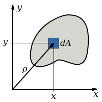
The equation describing the polar moment of inertia is a multiple integral over the cross-sectional area, , of the object.


Where, is the distance to the element .


Substituting the and components, using the Pythagorean theorem:


Given the planar second moments of area equations, where:


It is shown that the polar moment of inertia can be described as the summation of the and planar moments of inertia, and

This is also shown in the perpendicular axis theorem.[2] For objects that have rotational symmetry, such as a cylinder or hollow tube, the equation can be simplified to:
- or


For a circular section with radius r:

Unit
The SI unit for polar moment of inertia, like the area moment of inertia, is meters to the fourth power (m4), and inches to the fourth power (in4) in imperial units.
Limitations
The polar moment of inertia is insufficient for use to analyze beams and shafts with non-circular cross-sections, due their tendency to warp when twisted, causing out-of-plane deformations. In such cases, a torsion constant should be substituted, where an appropriate deformation constant is included to compensate for the warping effect. Within this, there are articles that differentiate between the polar moment of inertia, , and the torsional constant, , no longer using to describe the polar moment of inertia. [3]
In objects with significant cross-sectional variation (along the axis of the applied torque), which cannot be analyzed in segments, a more complex approach may have to be used. See 3-D elasticity.
Application
Though the polar moment of inertia is most often used to calculate the angular displacement of an object subjected to a moment (torque) applied parallel to the cross-section, it must be noted that the provided value of rigidity does not have any bearing on the torsional resistance provided to an object as a function of its constituent materials. The rigidity provided by an object's material is a characteristic of its shear modulus, . Combining these two features, one is able to calculate a shaft's angular deflection, , due to the applied torque, :


Where is the length of the shaft and is the applied torque. As shown, the larger the material's shear modulus and polar moment of area (i.e. larger cross-sectional area), the greater resistance to torsional deflection.

The polar moment of area appears in the formulae that describe torsional stress and angular displacement.
Torsional stresses:

Where is the torsional shear stress, is the applied torque, is the distance from the central axis, and is the polar moment of area.


Note: In a circular shaft, the shear stress is maximal at the surface of the shaft.
Sample calculation

Calculation of the steam turbine shaft radius for a turboset:
Assumptions:
- Power carried by the shaft is 1000 MW; this is typical for a large nuclear power plant.
- Yield stress of the steel used to make the shaft (τyield) is: 250 × 106 N/m².
- Electricity has a frequency of 50 Hz; this is the typical frequency in Europe. In North America the frequency is 60 Hz. This is assuming that there is a 1:1 correlation between rotational velocity of turbine and the frequency of mains power.
The angular frequency can be calculated with the following formula:

The torque carried by the shaft is related to the power by the following equation:

The angular frequency is therefore 314.16 rad/s and the torque 3.1831 × 10⁶ N·m.
The maximal torque is:

After substitution of the polar moment of inertia the following expression is obtained:
![{\displaystyle r={\sqrt[{3}]{\frac {2T_{\max }}{\pi \tau _{\max }}}}}](../I/m/edf0208971dd63eef9992bc09728d198e17800e3.svg)
The radius is 0.200 m. If one adds a factor of safety of 5 and re-calculates the radius with the maximal stress equal to the yield stress/5 the result is a radius of 0.343 m, or a diameter of 69 cm, the approximate size of a turboset shaft in a nuclear power plant.
Comparing polar and mass moments of inertia
Hollow Cylinder
Polar moment of inertia:

Mass moment of inertia:

Solid cylinder Polar moment of inertia

Mass moment of inertia

where:
- is the inner diameter in meters {m}
- is the outer diameter in meters {m}
- is the mass moment of inertia in kg·m2
- is the polar moment of inertia in meters to the fourth power {m^4}
- is the length of cylinder in meters {m}
- is the specific mass in kg/m3


See also
References
- ↑ Ugural AC, Fenster SK. Advanced Strength and Applied Elasticity. 3rd Ed. Prentice-Hall Inc. Englewood Cliffs, NJ. 1995. ISBN 0-13-137589-X.
- ↑ http://www.efunda.com/math/areas/MomentOfInertia.cfm
- ↑ "What is the difference between the Polar Moment of Inertia, IPIP and the torsional constant, JTJT of a cross section?".
|first1=missing|last1=in Authors list (help)
External links
- Torsion of Shafts - engineeringtoolbox.com
- Elastic Properties and Young Modulus for some Materials - engineeringtoolbox.com
- Material Properties Database - matweb.com