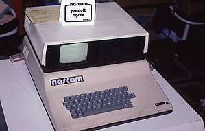
Nascom (computer kit)
 Nascom 2 Computer, September 1981 | |
| Developer | Chris Shelton[1] |
|---|---|
| Type | single-board computer |
| Release date |
Nascom 1: 1977 Nascom 2: 1979 |
The Nascom 1 and 2 were single-board computer kits issued in the United Kingdom in 1977 and 1979, respectively, based on the Zilog Z80 and including a keyboard and video interface, a serial port that could be used to store data on a tape cassette using the Kansas City standard, and two 8-bit parallel ports. At that time, including a full keyboard and video display interface was uncommon, as most microcomputer kits were then delivered with only a hexadecimal keypad and seven-segment display. To minimize cost, the buyer had to assemble a Nascom by hand-soldering about 3,000 joints on the single circuit board.
The original Nascom 1 was designed by Chris Shelton[1]. Shelton’s design work was outlined in a series of articles published between November 1977 and January 1979 by Wireless World magazine[2].
| Model | Nascom 1 | Nascom 2 |
|---|---|---|
| Introduced | December 1977 | December 1979 |
| MSRP (price) | £197.50 | £225 |
| CPU (µP) | Zilog Z80 | Zilog Z80A |
| CPU speed | 2 MHz | 2 or 4 MHz (switch on main board) |
| Monitor/OS* | NAS-BUG 1 (1 KB EPROM) | NAS-SYS 1, most were shipped with NAS-SYS 3 (2 KB ROM) |
| RAM | 2 KB (1 KB used for display), exp. to 64 KB | 8 KB, exp. to 1 MB |
| Discontinued | 1979 | 1983 |
| * A debug monitor and simple operating system (OS) was included with the devices. CP/M versions 1.4, 2.2 and 3.0 were also available later. | ||
Documentation
The Nascom 1 and Nascom 2 were supplied with full documentation including circuit schematics, construction guide, datasheets for some components and assembly listing for the ROM monitor. An annotated disassembly listing of the Nascom 2 Microsoft ROM BASIC was published[3] and the code was subsequently re-purposed in retrocomputing projects such as Grant Searle's Multicomp and Spencer Owen's RC2014. The source code can now be found on Github.[4]
Hardware
The Nascom 1[5] and Nascom 2[6] hardware designs had these features in common:
- A 16MHz crystal biased into oscillation and then divided down to create the clocks for the CPU, the serial communications and the video interface
- A Z80/Z80A CPU
- A Z80/Z80A PIO
- A Harris 6402 UART (or equivalent) that could be used either to communicate with a serial device (e.g. RS232 terminal or printer) or to save and load data using a domestic compact cassette recorder.
- A memory-mapped video display and a UHF video modulator capable of driving a domestic TV
- Circuitry decoded on IO port 0 to control a software-scanned keyboard, to drive a LED ("DRIVE") and to generate a timed non-maskable interrupt (NMI) that was used to provide a hardware single-step capabiity
- An LED ("HALT") on the Z80-CPU "/HALT" output, to provide a visual indication that the CPU was halted.
The I/O address map was common between the Nascom 1 and Nascom 2 designs, and the memory address map of the Nascom 2 was a superset of the Nascom 1 memory address map; this allowed a high degree of software compatibility between the two machines.
The Nascom 1 was implemented entirely using off-the-shelf integrated-circuits and other electronic components. The Nascom 2 used 4, 16-pin bipolar PROMs which acted as glue logic for decode functions ("N2MD" for memory decode, "N2IO" for I/O decode, "N2V" for video decode and N2DB" for data bus buffer control).
The Nascom 2 had these additional features that were not present on the Nascom 1:
- Timed reset to reset the CPU without interrupting the periodic refresh cycles produced by the Z80
- Gating to reset the Z80-PIO (the Z80-PIO has no dedicated reset input)
- A reset-jump circuit that allowed the Z80-CPU to start execution from any 4-Kbyte boundary after reset (the Z80-CPU usually fetches from address 0 after reset). This allowed, for example, control to be passed straight to the BASIC interpreter after reset.
- Microsoft BASIC in an 8Kbyte ROM.
- Two groups of 4 uncommitted 24-pin DIL sockets. Each group could be configured to accommodate 1Kx8 ROM or RAM devices and decoded at a start address of 0x1000, 0x2000, 0xB000, 0xC000 or 0xD000.
- A 24-pin DIL socket that could accommodate a second character-generator ROM
- Full buffering of the CPU address, data and control to generate the "NAS-BUS" expansion bus.
The I/O address map was decoded as follows:
| I/O Port address | Function |
|---|---|
| 0x0 (read) | Read keyboard state |
| 0x0 (write) | Control keyboard, control single-step (NMI) logic, control "DRIVE" LED |
| 0x1 | UART Data |
| 0x2 | UART Control/Status |
| 0x3 | Unused |
| 0x4 | Z80-PIO Data Port A |
| 0x5 | Z80-PIO Data Port B |
| 0x6 | Z80-PIO Control Port A |
| 0x7 | Z80-PIO Control Port B |
On an unexpanded system, these 8 ports were repeated through the whole of the I/O address space. On an expanded system, the bus signal /NASIO allowed control of the I/O address space.
The memory address map was decoded as follows:
| Address | Nascom 1 | Nascom 2 |
|---|---|---|
| 0x0000-0x07FF | Monitor (NASBUG, T4, NAS-SYS1, NAS-SYS3)
1 or 2 1Kbyte 2708 EPROM |
Monitor (NAS-SYS1 or NAS-SYS3)
2Kbyte ROM or 2716 EPROM |
| 0x0800-0x0BFF | Video RAM | Video RAM |
| 0x0C00-0x0FFF | Workspace RAM | Workspace RAM |
| 0x1000-0x1FFF | Decoded on board. Usually used for RAM (4, 1Kbyte devices) | |
| 0x2000-0x2FFF | Decoded on board. Usually used for RAM (4, 1Kbyte devices) | |
| 0xB000-0xBFFF | Decoded on board. Usually used for EPROM (4, 1Kbyte 2708 devices) | |
| 0xC000-0xCFFF | Decoded on board. Usually used for EPROM (4, 1Kbyte 2708 devices) | |
| 0xD000-0xDFFF | Decoded on board. Usually used for EPROM (4, 1Kbyte 2708 devices) | |
| 0xE000-0xFFFF | Microsoft 8Kbyte ROM BASIC |
Keyboard
The keyboard used Licon keys in a matrix arrangement which was scanned under software control. The Nascom 1 had 47 keys. The Nascom 2 had 10 additional keys (GRAPH, which toggled bit 7, CTRL, a second SHIFT key, 4 cursor direction keys, LF/CH and keys for [ and ]).
Video Display
The display of the Nascom 1 and 2 was memory-mapped and consisted of 16 rows of 48 characters. Each row of characters used 64 consecutive memory locations; the extra 16 characters in each line were "hidden" by the video blanking circuitry.
Scrolling was implemented under software control. Due to an idiosyncrasy of the video memory decoding on the Nascom 1 (which was then retained on the Nascom 2), the lines were decoded discontiguously, with the top line of the display being the 16th region of memory. The top line was not scrolled, except by the NASCOM CP/M implementation.
The Nascom 1 used a MCM6576P character generator to display 128 characters (bit 7 of the memory was ignored). The Nascom 2 used an identical character set but implemented it in a ROM that was footprint compatible with a 2716 2Kbyte device. The Nascom 2 allowed a second character generator ROM (or EPROM) to be fitted (approximate price £20 in 1980) . The so-called NAS-GRA ROM was used to display characters with the byte codes 0x80--0xFF. The built-in Microsoft BASIC (8K ROM) interpreter could use these graphics to create a crude, blocky 96×48 graphics display.
The design of the video display required that the CPU and the video circuitry shared access to the video RAM (the CPU had read/write access and the video circuitry had read-only access). If the CPU and the video circuitry accesses the video RAM simultaneously, the CPU was given priority and the video circuitry would read incorrect data. On the Nascom 1 this gave rise to white flicker on the screen that was termed "snow". The International Nascom Microcomputer Club (INMC) published a "snow plough" design that reduced the effect by blanking the video when simultaneous access occurred[7]. The Nascom 2 used a slightly different design but still allowed contention to occur, this time giving rise to black flicker (blanking) on the screen.
Software
Initially, software was made available either on cassette tape or programmed into one or more EPROMs (usually 1kbyte 2708 devices).
The predecessor of Borland's very successful Turbo Pascal compiler and integrated development environment (IDE) for CP/M and DOS was developed by Anders Hejlsberg of Blue Label Software for the Nascom 2, under the name Blue Label Software Pascal, or BLS Pascal.
In 1979 the Nascom 2 came with an onboard ROM with early Microsoft Basic 8k interpreter. The manual was a Brown Padded loose leaf ring binder.
Expansion
An interface bus, initially proprietary but quickly superseded by the 80-bus, allowed many other cards to be added to the Nascom, a progression which led to the Gemini 80-bus system which was, for a while, used as an industrial process controller. British Cellophane used several to continuously monitor thickness gauges attached to plastic sheet production lines. An 80-bus compatible network card enabled both Nascoms and Geminis to be used in office environments.
Miscellaneous
In the early 1980s, the name of the town of Kenilworth was used by one of the first generation of computer retailers, a company called Kenilworth Computers based near the Clock Tower, when it released a version of the Nascom microcomputer with the selling point that it was robust enough to be used by agriculture.
References
- 1 2 UK micro pioneer Chris Shelton: The mind behind the Nascom 1
- ↑ "Wireless World". http://www.nascomhomepage.com. November 1977. External link in
|website=(help) - ↑ Lloyd-Parker, Carl (1983). "The workings of Nascom ROM BASIC v4.7" (PDF). https://tupel.jloh.de/nascom/magazines/80-bus-news/. Retrieved 28 May 2018. External link in
|website=(help) - ↑ "Nascom ROM BASIC". Github.
- ↑ "Nascom 1 Schematics" (PDF). The Nascom Home Page. April 1978.
- ↑ "Nascom 2 schematics" (PDF). The Nascom Home Page. 16 June 1979.
- ↑ Hunt, Dave (1979). "INMC News issue 2" (PDF). https://80bus.co.uk.mirror.jloh.de/publications/magazines/. External link in
|website=(help)
External links
- Dedicated user group
- Nascom homepage, with software and documentation
- Nascom Nostalgia
- Nascom / Gemini / 80 Bus, large archive of material
- Working Nascoms in the UK