Light switch
In electrical wiring, a light switch is a switch most commonly used to operate electric lights, permanently connected equipment, or electrical outlets. Portable lamps such as table lamps may have a light switch mounted on the socket, base, or in-line with the cord. Manually operated on/off switches may be substituted by dimmer switches that allow controlling the brightness of lamps as well as turning them on or off, time-controlled switches, occupancy-sensing switches, and remotely controlled switches and dimmers. Light switches are also found in flashlights, vehicles, and other devices.
Wall-mounted switches
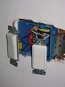
Switches for lighting may be in hand-held devices, moving vehicles, and buildings. Residential and commercial buildings usually have wall-mounted light switches to control lighting within a room. Mounting height, visibility, and other design factors vary from country to country. The switch mounting boxes, or enclosures are often recessed within a finished wall. Surface mounting of enclosures is also fairly common though is seen more in commercial industrial and outbuilding settings than in residential structures. These light switch boxes (a pattress box) are designed to house and mount the switch(s), protect the wiring and contain any heat or fire. Each kind uses some form of a plastic, ceramic, or metal cover to prevent accidental contact with live terminals of the switch. Wall plates are available in different styles and colours to blend in with the style of a room, also available in weatherproof varieties for outdoors. These covers are usually quite easy to mount.
History, culture, and style

The first light switch employing "quick-break technology" was invented by John Henry Holmes in 1884 in the Shieldfield district of Newcastle upon Tyne.[2] The "quick-break" switch overcame the problem of a switch's contacts developing electric arcing whenever the circuit was opened or closed. Arcing would cause pitting on one contact and the build-up of residue on the other, and the switch's useful life would be diminished. Holmes' invention ensured that the contacts would separate or come together very quickly, however much or little pressure was exerted by the user on the switch actuator. The action of this "quick break" mechanism meant that there was insufficient time for an arc to form, and the switch would thus have a long working life. This "quick break" technology is still in use in almost every ordinary light switch in the world today, numbering in the billions, as well as in many other forms of electric switch.
The toggle light switch was invented in 1917 by William J. Newton.[3]
As a component of an electrical wiring or home wiring system, the installation of light switches is regulated by some authority concerned with safety and standards. In different countries the standard dimensions of the wall mounting hardware (boxes, plates, etc.) may differ. Since the face-plates used must cover this hardware, these standards determine the minimum sizes of all wall mounted equipment. Hence, the shape and size of the boxes and face-plates, as well as what is integrated, varies from country to country.
The dimensions, mechanical designs, and even the general appearance of light switches have changed slowly over time. Switches typically remain in service for many decades, often being changed only when a portion of a house is rewired. It is not unusual to see century-old light switches still in functional use. Manufacturers introduce various new forms and styles, but for the most part decoration and fashion concerns are limited to the face-plates or wall-plates. Even the "modern" dimmer switch with knob is at least forty years old, and in even the newest construction the familiar toggle and rocker switch formats predominate.
Orientation
The direction which represents "on" also varies by country. In the US and Canada, it is usual for the "on" position of a toggle switch to be "up", whereas in many other countries such as the UK, Ireland, Australia, and New Zealand it is "down". (In multiway switching, the correspondence between a single switch's state and whether lights are on or off depends on the state of the other switch[es] in the circuit.)
Design
The switches may be single or multiple, designed for indoor or outdoor use. Optional extras may include dimmer-controls, environmental protection, weather and security protection. In residential and light commercial lighting systems, the light switch directly controls the circuit feeding the lamps. In larger lighting systems, for example warehouses or outdoor lighting systems, the required current may be too high for a manual switch. In these systems light switches control lighting contactors, a relay that allows the manual light switch to operate on a lower voltage or with smaller wiring than would be required in the main lighting circuit.
In the UK, putting 13 Amp BS1363 sockets on a lighting circuit is discouraged (although not outright prohibited), but 2 Amp or 5 Amp BS546 outlets are often put on lighting circuits to allow control of free-standing lamps from the room's light switches. In North American site-built and mobile homes, often living rooms and bedrooms have a switched receptacle for a floor or table lamp.
Internal operation
The contacts of a switch are under their greatest stress while opening or closing. As the switch is closed, the resistance between the contacts changes from almost infinite to almost zero. At infinite resistance, no current flows and no power is dissipated. At zero resistance, there is no voltage drop and no power is dissipated. However, while the contacts change state, there is a brief instant of partial contact when resistance is neither zero nor infinite, and electrical power is converted into heat. If the heating is excessive, the contacts may be damaged, or may even weld themselves closed.
A switch should be designed to make its transition as swiftly as possible. This is achieved by the initial operation of the switch lever mechanism storing potential energy, usually as mechanical stress in a spring. When sufficient mechanical energy is stored, the mechanism in the switch "breaks over", and quickly drives the contacts through the transition from open to closed, or closed to open, without further action by the switch operator. This quick-break action of the switch is essential to a long life for the switch contacts, as described in Holmes' 1884 patent.
While the contacts are separating, any electrical energy stored in the inductance of the circuit being disconnected is dissipated as an arc within the switch, prolonging the transition and worsening the heating effect on the contacts. Switches are commonly rated by the current they are designed to break, under specified voltage and power factor conditions, as this is the most stringent limitation.
The arc that results when the switch opens erodes the switch contacts. Therefore, any switch has a finite life, often rated at a given number of cycles of disconnection at a specified current. Operation outside of its specified operating capacity will drastically shorten the life of the switch.
To combat contact corrosion, a switch is usually designed to have a "wipe" action so that the contacts are cleaned. Large switches may be designed with a supplemental replaceable contact that closes and opens before the main contact, protecting the main current-carrying contacts from wear due to arcing. The contact area of the switch is constructed of materials that resist corrosion and arcing.
Many higher current switch designs rely on the separation arc to assist in dispersing contact corrosion. A switch designed for high-current high-voltage use may become unreliable if operated at very low currents and low voltages, because a non-conductive oxide layer builds up without an arc to disperse it.
Two kinds of sparks may occur during switch operation. On closure, a few sparks, like those from a flint-and-steel, may appear as a tiny bit of metal is heated by friction to incandescence, melted, and thrown off. On opening, a bluish arc may occur, with a detectable "electrical" (ozone) odor. Subsequently, the contacts may be seen to be darkened and pitted. Damaged contacts have higher resistance, rendering them more vulnerable to further damage and causing a cycle in which the contacts soon may fail completely.
To make a switch safe, durable, and reliable, it must be designed so that the contacts are held firmly together under positive force when the switch is closed. It should be designed so that, regardless of how the operator manipulates the actuator, the contacts always close or open quickly.
In the construction of many small switches, the spring that stores the mechanical energy necessary for the snap action of the switch mechanism is made of a beryllium copper alloy that is hardened to form a spring as part of the fabrication of the contact. The same part often also forms the body of the contact itself, and is thus the current path. Abusing the switch mechanism to hold the contacts in a transition state, or severely overloading the switch, will heat and thus anneal the spring, reducing or eliminating the "snap action" of the switch, leading to slower transitions, more energy dissipated in the switch, and progressive failure.
Variations on design
Push button

The push-button light switch has two buttons: one that closes the contacts and one that opens the contacts. Pushing the raised button opens or closes the contacts and pops out the previously depressed button so the process can be reversed. Push-button switch reproductions are available on the market today for vintage or authentic styling.
Toggle
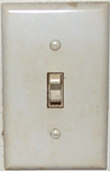
The toggle mechanism provides "snap-action" through the use of an "over-center" geometry. The design was patented in 1916 by William J. Newton and Morris Goldberg.[3] The switch actuator does not control the contacts directly, but through an intermediate arrangement of springs and levers. Turning the actuator does not initially cause any motion of the contacts, which in fact continue to be positively held open by the force of the spring. Turning the actuator gradually stretches the spring. When the mechanism passes over the center point, the spring energy is released and the spring, rather than the actuator, drives the contacts rapidly and forcibly to the closed position with an audible "snapping" sound. This mechanism is safe, reliable, and durable, but produces a loud snap or click.
As of 2004 in the United States, the toggle switch mechanism was almost entirely supplanted by "quiet switch" mechanisms. "Quiet switch" mechanisms still possess a form of snap action, but it is very weak as compared to its predecessor. They are therefore equipped with larger, high-quality contacts that are capable of switching domestic loads without damage, despite the less-positive action.
Illuminated switch

Illuminated switches incorporate a small neon lamp or LED, allowing the user easily to locate the switch in the dark. Household illuminated switches were introduced in the mid-1950s.[4]
Single-pole illuminated switches derive the power to energize their in-built illuminating source (usually, a "neon" lamp) from the current passing through the lamp(s) which they control. Such switches work satisfactorily with incandescent lamps, halogen lighting, and non-electronic fluorescent fixtures, because the small current required for the switch's illuminating source is too small to produce any visible light from such devices controlled by the illuminated switch. However, if they control only compact fluorescent lamps (CFLs) and/or LED lamps, the small amount of current required to energize the lighting source within switch also slowly charges the internal input capacitor in the electronic ballast of the CFL or LED until the voltage across it rises to the point where it produces a brief discharge through the CFL. This cycle may repeat indefinitely, resulting in repetitive brief flashing of the lamp(s) (and the light inside the switch) while the illuminated switch is in the "off" position.
Rocker
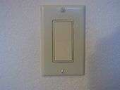

An alternative design to the toggle switch is the rocker switch. Large switches of this design are commonly known as "decorator style" in the United States. Switches of this design sit almost flush with the wall plate, and are activated by "rocking" a flat, broad lever, rather than pushing a short protruding actuator up or down.
In Europe, Hong Kong, Malaysia, Singapore, and India this type is near-universal, and toggle style switches would be considered old-fashioned.
Australian rocker switches
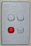
In Australia and New Zealand, a small rocker switch is almost universally used, in the form of a 16 mm (0.63 in) switch mechanism, which is mounted from behind into a wall-plate—attaching via mounting lugs, as shown in the photo on the left. A slightly larger "cover plate", supplied with the wall-plate, or additional to it, then clips over the assembly, as an additional insulating barrier covering the deep set wall-plate mounting screws - which are "deep set" to prevent inadvertent human contact. The "cover plate" can be removed without the use of tools, such as when wall painting is required.
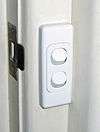
While larger "decorator" style switches are readily available in Australia, the advantage of the smaller mechanisms is that wall-plates are available to mount from one to six individual switch mechanisms, or other correspondingly sized "mechanisms" - such as dimmers and indicator lights - in the same space as one (or two) switches of larger design could be mounted. Since the mechanisms are small, they can also be mounted into "architrave" plates, for mounting in positions where it is not possible to mount a "standard" sized wall-plate. An example is shown in the picture below on the right. All of the switch mechanisms have no exposed metal parts requiring grounding (earthing). While switches, wall-plates, and cover plates from different manufacturers tend not to be interchangeable, switch mechanisms of this type have been available in Australia since 1971.[5]
The keystone module system for extra-low voltage electrical jacks (patented in 1995) is somewhat similar in appearance to these modules, but the design of the keystone mountings are different, and keystone modules can be removed without a tool. (A similar system, but with bigger switches, is used in Italy.)
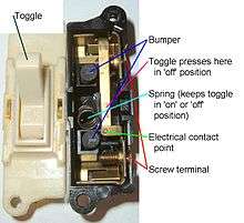
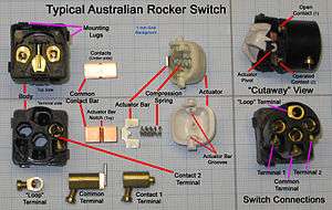
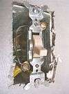
As shown in the disassembly photo, the switch actuator pivots in two holes in the sides of the plastic switch body. An actuator bar slides in two grooves inside the actuator, pressed down by a compression spring into a notch in the common contact bar. The common contact bar is free to rock on a small diameter rod, welded to the common terminal. However, because of the pressure applied by the compression spring, the common contact bar will always be held against one of the two contacts.
When the actuator is moved, mechanical energy is stored in the compression spring until the actuator passes its mid-position. At that time, the common contact bar is forced in the opposite direction by the compression spring, acting via the actuator bar, thus breaking the connection with the existing contact and making connection with the other contact. The common contact bar is made of copper, with an inlay of harder contact metal on the underside. While it is free to move the required distance lengthwise, it is constrained from moving sideways by the construction of the molded plastic body.
The screw terminals are hollow and allow up to at least three 1 mm (CSA) wires, twisted together, to be inserted to a depth of up to 10 millimetres (0.39 in) and secured with a set screw. The contact terminal set screws are installed at a slight angle to allow easier screwdriver access after the switch mechanism has been installed into a wall-plate - before fixing the wall-plate to the wall. Also shown is a "loop" connection terminal. This terminal plays no part in the action of the switch but, because there is available space, it is provided as an insulated terminal for joining other wires, if required (such as the neutral wires). Each Australian rocker switch mechanism is actually a single-pole, double-throw (SPDT) Switch, also known as a "two-way switch", and has three terminals.
A switch of basically the same design is also used on Australian power outlet wall-plates. It is now extremely rare to find any other type of switch in Australian homes, although the Australian Wiring Standard AS 3112 does not forbid other types. While many variations of Australian designs and cover plates are available, some designers and renovators may import UK- and European-designed switches when they desire a particular finish. However, while standard Australian wall mounting plates have the same dimensions as those used in North America, they have different dimensions from those used in the UK or Europe.
Switches (and other mechanisms) of this Australian design series are currently available in the UK (and other countries), together with wall-plates appropriate to the mounting standards of the countries concerned. [6]
For a short time, Australian rocker switches were exported to the United States in the 1980s. Although the switches had adequate ratings for usage on 120 V circuits and had advantages of compactness and distinctive appearance, they failed to establish themselves in the American market.
Tamper resistant
Where lighting circuits must not be accidentally switched off, for example, corridor and restroom lighting controls in public buildings such as schools, a tamper-resistant switch may be installed. These require a key to operate and so discourage casual or accidental operation of the switch. [8]
Voltage class
In North American commercial and industrial lighting installations, lighting installed on 480Y/277 V 3-phase circuits uses voltages higher than the rating of common 120 V switches.
Mercury switch
Before the 1970s, mercury switches were popular. Their cost was more than that of other designs, but they were totally silent in operation. The switch actuator tipped a sealed glass vial connected via flexible leads, causing a drop of liquid metallic mercury to roll from one end to the other. When it arrived at the contact end, the drop of mercury bridged a pair of contacts to complete the circuit. Many of these switches were also equipped with a neon lamp connected across the contacts, and thus in series with the electrical load. This caused the indicator to glow faintly when the switch was off, as an aid to finding the switch in a dark room.
Although the glass vial was hermetically sealed, concerns about the release of toxic mercury when the switches were eventually damaged or disposed of led to the abandonment of this design for new products.
Pull-chain or pull-cord
A light switch combined with a light socket is sometimes installed in basement or utility areas of homes. The switch is operated by a pull chain or cord. It is also possible to have the cord-operated switch separate from the light socket, which is particularly common in British bathrooms. Until 2001, UK wiring regulations required that all bathroom switches were operated by pull cords.
Dimmer switch
A dimmer switch, properly called a dimmer control, contains a solid-state circuit to allow changing the brightness by reducing the average voltage applied to the lamp.
Electronic switches

In principle, it is easy to design silent switches in which the mechanical contacts do not directly control the current, but simply signal a solid-state device such as a thyristor to complete the circuit. Many variations on this theme have been created and marketed. "Touch-plate" devices can be operated by touching or merely waving a hand near the switch. Touch switches have no moving parts and electronically switch the light circuit. As of 2006 these remain specialty items. Electronic switches provide flexibility in terms of different interfaces for their operations, such as touch plates, soft-touch controls, pressure or light sensor based control, interactive touch-screens (which are widely used in aircraft for lighting control), and others.
Public buildings such as hospitals frequently save energy by using motion detector switches, also known as occupancy sensors. The occupancy sensors can also be used in residential applications such as in bathrooms, garages, and hallways.[10]
A wireless light switch provides remote control of lighting using a hand-held transmitter. While the controlling device may be a unit dedicated to this purpose, increasingly such switches may be controlled by the technology (such as Bluetooth or Wi-Fi) now found in smartphones.
Wired remote control of lighting switches is also possible using, for example, X10 signaling over the power wires.
Multiway switching
Two or more light switches can be interconnected to allow control of lighting from, for example, two ends of a long hallway or landings at the upper and lower landings of a flight of stairs. Multiway switching is done using special switches that have additional contacts.
Materials
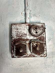
Earlier switches were made of porcelain in the surface-mounted version and operated as a rotary switch with a rotary mechanism. Later, more durable Bakelite was used. Today they are made of modern plastics. In some cases, especially in hospitals and other public facilities, exposed parts of light switches are made of antimicrobial materials such as copper, for infection control.
See also
References
- ↑ "Decora®". www.leviton.com. Retrieved 2018-09-06.
- ↑ Electric Light Years 1878-1899 - England's North East Archived 2015-05-20 at the Wayback Machine.
- 1 2 "Flush Switch" (PDF). Google Patents. Jul 17, 1917. Retrieved 2011-11-11.
- ↑ "What's New for Your Home". Popular Mechanics: 131. March 1955. Archived from the original on 27 May 2013. Retrieved 12 February 2013.
- ↑ Clipsal History Timeline Archived 2014-03-07 at the Wayback Machine.
- ↑ "Archived copy" (PDF). Archived from the original (PDF) on 2013-04-18. Retrieved 2014-03-13.
- ↑ "Product Bulletin for 30 Amp AC Toggle Switches". Leviton. Retrieved 1 September 2014.
- ↑ "Low-Cost Security Measures for School Facilities" (PDF). National Clearinghouse for Educational Facilities. Archived (PDF) from the original on 25 May 2012. Retrieved 1 September 2014.
- ↑ "How Do Lighting Controls Work?". HeathCo LLC. Archived from the original on 13 September 2014. Retrieved 6 September 2014.
- ↑ Product Specification for PR150-1L/PR180-1L. Leviton. Retrieved 6 September 2014.
External links
