Pulse-code modulation
| Filename extension |
.L16, .WAV, .AIFF, .AU, .PCM[1] |
|---|---|
| Internet media type |
audio/L16, audio/L8,[2] audio/L20, audio/L24[3][4] |
| Type code | "AIFF" for L16,[1] none[3] |
| Magic number | varies |
| Type of format | uncompressed audio |
| Contained by | Audio CD, AES3, WAV, AIFF, AU, M2TS, VOB, and many others |
| Extended from | PCM |
| Passband modulation |
|---|
| Analog modulation |
| Digital modulation |
| Hierarchical modulation |
| Spread spectrum |
| See also |
|
Pulse-code modulation (PCM) is a method used to digitally represent sampled analog signals. It is the standard form of digital audio in computers, compact discs, digital telephony and other digital audio applications. In a PCM stream, the amplitude of the analog signal is sampled regularly at uniform intervals, and each sample is quantized to the nearest value within a range of digital steps.
Linear pulse-code modulation (LPCM) is a specific type of PCM where the quantization levels are linearly uniform.[5] This is in contrast to PCM encodings where quantization levels vary as a function of amplitude (as with the A-law algorithm or the μ-law algorithm). Though PCM is a more general term, it is often used to describe data encoded as LPCM.
A PCM stream has two basic properties that determine the stream's fidelity to the original analog signal: the sampling rate, which is the number of times per second that samples are taken; and the bit depth, which determines the number of possible digital values that can be used to represent each sample.
History
Early electrical communications started to sample signals in order to multiplex samples from multiple telegraphy sources and to convey them over a single telegraph cable. The American inventor Moses G. Farmer conveyed telegraph time-division multiplexing (TDM) as early as 1853. Electrical engineer W. M. Miner, in 1903, used an electro-mechanical commutator for time-division multiplexing multiple telegraph signals; he also applied this technology to telephony. He obtained intelligible speech from channels sampled at a rate above 3500–4300 Hz; lower rates proved unsatisfactory.
In 1920, the Bartlane cable picture transmission system used telegraph signaling of characters punched in paper tape to send samples of images quantized to 5 levels.[6] In 1926, Paul M. Rainey of Western Electric patented a facsimile machine which transmitted its signal using 5-bit PCM, encoded by an opto-mechanical analog-to-digital converter.[7] The machine did not go into production.[8]
British engineer Alec Reeves, unaware of previous work, conceived the use of PCM for voice communication in 1937 while working for International Telephone and Telegraph in France. He described the theory and advantages, but no practical application resulted. Reeves filed for a French patent in 1938, and his US patent was granted in 1943.[9] By this time Reeves had started working at the Telecommunications Research Establishment.[8]
The first transmission of speech by digital techniques, the SIGSALY encryption equipment, conveyed high-level Allied communications during World War II. In 1943 the Bell Labs researchers who designed the SIGSALY system became aware of the use of PCM binary coding as already proposed by Alec Reeves. In 1949, for the Canadian Navy's DATAR system, Ferranti Canada built a working PCM radio system that was able to transmit digitized radar data over long distances.[10]
PCM in the late 1940s and early 1950s used a cathode-ray coding tube with a plate electrode having encoding perforations.[11] As in an oscilloscope, the beam was swept horizontally at the sample rate while the vertical deflection was controlled by the input analog signal, causing the beam to pass through higher or lower portions of the perforated plate. The plate collected or passed the beam, producing current variations in binary code, one bit at a time. Rather than natural binary, the grid of Goodall's later tube was perforated to produce a glitch-free Gray code, and produced all bits simultaneously by using a fan beam instead of a scanning beam.[12]
In the United States, the National Inventors Hall of Fame has honored Bernard M. Oliver[13] and Claude Shannon[14] as the inventors of PCM,[15] as described in "Communication System Employing Pulse Code Modulation", U.S. Patent 2,801,281 filed in 1946 and 1952, granted in 1956. Another patent by the same title was filed by John R. Pierce in 1945, and issued in 1948: U.S. Patent 2,437,707. The three of them published "The Philosophy of PCM" in 1948.[16]
The T-carrier system, introduced in 1961, uses two twisted-pair transmission lines to carry 24 PCM telephone calls sampled at 8 kHz and 8-bit resolution. This development improved capacity and call quality compared to the previous frequency-division multiplexing schemes.
In 1967, the first PCM recorder was developed by NHK's research facilities in Japan.[17] The 30 kHz 12-bit device used a compander (similar to DBX Noise Reduction) to extend the dynamic range, and stored the signals on a video tape recorder. In 1969, NHK expanded the system's capabilities to 2-channel stereo and 32 kHz 13-bit resolution. In January 1971, using NHK's PCM recording system, engineers at Denon recorded the first commercial digital recordings.[note 1][17]
In 1972, Denon unveiled the first 8-channel digital recorder, the DN-023R, which used a 4-head open reel broadcast video tape recorder to record in 47.25 kHz, 13-bit PCM audio.[note 2] In 1977, Denon developed the portable PCM recording system, the DN-034R. Like the DN-023R, it recorded 8 channels at 47.25 kHz, but it used 14-bits "with emphasis, making it equivalent to 15.5 bits."[17]
In 1973, adaptive differential pulse-code modulation (ADPCM) was developed, by P. Cummiskey, Nikil S. Jayant and James L. Flanagan.[18]
The compact disc (CD) brought PCM to consumer audio applications with its introduction in 1982. The CD uses a 44,100 Hz sampling frequency and 16-bit resolution and stores up to 80 minutes of stereo audio per disc.
Implementations
PCM is the method of encoding typically used for uncompressed digital audio.[note 3]
- The 4ESS switch introduced time-division switching into the US telephone system in 1976, based on medium scale integrated circuit technology.[19]
- LPCM is used for the lossless encoding of audio data in the Compact disc Red Book standard (informally also known as Audio CD), introduced in 1982.
- AES3 (specified in 1985, upon which S/PDIF is based) is a particular format using LPCM.
- LaserDiscs with digital sound have an LPCM track on the digital channel.
- On PCs, PCM and LPCM often refer to the format used in WAV (defined in 1991) and AIFF audio container formats (defined in 1988). LPCM data may also be stored in other formats such as AU, raw audio format (header-less file) and various multimedia container formats.
- LPCM has been defined as a part of the DVD (since 1995) and Blu-ray (since 2006) standards.[20][21][22] It is also defined as a part of various digital video and audio storage formats (e.g. DV since 1995,[23] AVCHD since 2006[24]).
- LPCM is used by HDMI (defined in 2002), a single-cable digital audio/video connector interface for transmitting uncompressed digital data.
- RF64 container format (defined in 2007) uses LPCM and also allows non-PCM bitstream storage: various compression formats contained in the RF64 file as data bursts (Dolby E, Dolby AC3, DTS, MPEG-1/MPEG-2 Audio) can be "disguised" as PCM linear.[25]
Modulation
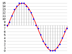
In the diagram, a sine wave (red curve) is sampled and quantized for PCM. The sine wave is sampled at regular intervals, shown as vertical lines. For each sample, one of the available values (on the y-axis) is chosen. The PCM process is commonly implemented on a single integrated circuit called an analog-to-digital converter (ADC). This produces a fully discrete representation of the input signal (blue points) that can be easily encoded as digital data for storage or manipulation. Several PCM streams could also be multiplexed into a larger aggregate data stream, generally for transmission of multiple streams over a single physical link. One technique is called time-division multiplexing (TDM) and is widely used, notably in the modern public telephone system.
Demodulation
To recover the original signal from the sampled data, a "demodulator" can apply the procedure of modulation in reverse. After each sampling period, the demodulator reads the next value and shifts the output signal to the new value. As a result of these transitions, the signal has a significant amount of high-frequency energy caused by aliasing. To remove these undesirable frequencies and leave the original signal, the demodulator passes the signal through analog filters that suppress energy outside the expected frequency range (greater than the Nyquist frequency ).[note 4] The sampling theorem shows PCM devices can operate without introducing distortions within their designed frequency bands if they provide a sampling frequency twice that of the input signal. For example, in telephony, the usable voice frequency band ranges from approximately 300 Hz to 3400 Hz. Therefore, according to the Nyquist–Shannon sampling theorem, the sampling frequency (8 kHz) must be at least twice the voice frequency (4 kHz) for effective reconstruction of the voice signal.

The electronics involved in producing an accurate analog signal from the discrete data are similar to those used for generating the digital signal. These devices are Digital-to-analog converters (DACs). They produce a voltage or current (depending on type) that represents the value presented on their digital inputs. This output would then generally be filtered and amplified for use.
Standard sampling precision and rates
Common sample depths for LPCM are 8, 16, 20 or 24 bits per sample.[1][2][3][26]
LPCM encodes a single sound channel. Support for multichannel audio depends on file format and relies on interweaving or synchronization of LPCM streams.[5][27] While two channels (stereo) is the most common format, some can support up to 8 audio channels (7.1 surround).[2][3]
Common sampling frequencies are 48 kHz as used with DVD format videos, or 44.1 kHz as used in Compact discs. Sampling frequencies of 96 kHz or 192 kHz can be used on some newer equipment, with the higher value equating to 6.144 megabit per second for two channels at 16-bit per sample value, but the benefits have been debated.[28] The bitrate limit for LPCM audio on DVD-Video is also 6.144 Mbit/s, allowing 8 channels (7.1 surround) × 48 kHz × 16-bit per sample = 6,144 kbit/s.
There is a L32 bit PCM, and there are many sound cards that support it.[29]
Limitations
There are potential sources of impairment implicit in any PCM system:
- Choosing a discrete value that is near but not exactly at the analog signal level for each sample leads to quantization error.[note 5]
- Between samples no measurement of the signal is made; the sampling theorem guarantees non-ambiguous representation and recovery of the signal only if it has no energy at frequency fs/2 or higher (one half the sampling frequency, known as the Nyquist frequency); higher frequencies will generally not be correctly represented or recovered.
- As samples are dependent on time, an accurate clock is required for accurate reproduction. If either the encoding or decoding clock is not stable, its frequency drift will directly affect the output quality of the device.[note 6]
Digitization as part of the PCM process
In conventional PCM, the analog signal may be processed (e.g., by amplitude compression) before being digitized. Once the signal is digitized, the PCM signal is usually subjected to further processing (e.g., digital data compression).
PCM with linear quantization is known as Linear PCM (LPCM).[30]
Some forms of PCM combine signal processing with coding. Older versions of these systems applied the processing in the analog domain as part of the analog-to-digital process; newer implementations do so in the digital domain. These simple techniques have been largely rendered obsolete by modern transform-based audio compression techniques.
- DPCM encodes the PCM values as differences between the current and the predicted value. An algorithm predicts the next sample based on the previous samples, and the encoder stores only the difference between this prediction and the actual value. If the prediction is reasonable, fewer bits can be used to represent the same information. For audio, this type of encoding reduces the number of bits required per sample by about 25% compared to PCM.
- Adaptive DPCM (ADPCM) is a variant of DPCM that varies the size of the quantization step, to allow further reduction of the required bandwidth for a given signal-to-noise ratio.
- Delta modulation is a form of DPCM which uses one bit per sample.
In telephony, a standard audio signal for a single phone call is encoded as 8,000 analog samples per second, of 8 bits each, giving a 64 kbit/s digital signal known as DS0. The default signal compression encoding on a DS0 is either μ-law (mu-law) PCM (North America and Japan) or A-law PCM (Europe and most of the rest of the world). These are logarithmic compression systems where a 12 or 13-bit linear PCM sample number is mapped into an 8-bit value. This system is described by international standard G.711. An alternative proposal for a floating point representation, with 5-bit mantissa and 3-bit exponent, was abandoned.
Where circuit costs are high and loss of voice quality is acceptable, it sometimes makes sense to compress the voice signal even further. An ADPCM algorithm is used to map a series of 8-bit µ-law or A-law PCM samples into a series of 4-bit ADPCM samples. In this way, the capacity of the line is doubled. The technique is detailed in the G.726 standard.
Later it was found that even further compression was possible and additional standards were published. Some of these international standards describe systems and ideas which are covered by privately owned patents and thus use of these standards requires payments to the patent holders.
Some ADPCM techniques are used in Voice over IP communications.
Encoding for serial transmission
PCM can be either return-to-zero (RZ) or non-return-to-zero (NRZ). For a NRZ system to be synchronized using in-band information, there must not be long sequences of identical symbols, such as ones or zeroes. For binary PCM systems, the density of 1-symbols is called ones-density.[31]
Ones-density is often controlled using precoding techniques such as Run Length Limited encoding, where the PCM code is expanded into a slightly longer code with a guaranteed bound on ones-density before modulation into the channel. In other cases, extra framing bits are added into the stream which guarantee at least occasional symbol transitions.
Another technique used to control ones-density is the use of a scrambler polynomial on the raw data which will tend to turn the raw data stream into a stream that looks pseudo-random, but where the raw stream can be recovered exactly by reversing the effect of the polynomial. In this case, long runs of zeroes or ones are still possible on the output, but are considered unlikely enough to be within normal engineering tolerance.
In other cases, the long term DC value of the modulated signal is important, as building up a DC offset will tend to bias detector circuits out of their operating range. In this case special measures are taken to keep a count of the cumulative DC offset, and to modify the codes if necessary to make the DC offset always tend back to zero.
Many of these codes are bipolar codes, where the pulses can be positive, negative or absent. In the typical alternate mark inversion code, non-zero pulses alternate between being positive and negative. These rules may be violated to generate special symbols used for framing or other special purposes.
Nomenclature
The word pulse in the term pulse-code modulation refers to the "pulses" to be found in the transmission line. This perhaps is a natural consequence of this technique having evolved alongside two analog methods, pulse width modulation and pulse position modulation, in which the information to be encoded is represented by discrete signal pulses of varying width or position, respectively. In this respect, PCM bears little resemblance to these other forms of signal encoding, except that all can be used in time division multiplexing, and the numbers of the PCM codes are represented as electrical pulses. The device that performs the coding and decoding function in a telephone, or other, circuit is called a codec.
See also
- Beta encoder
- Equivalent pulse code modulation noise
- Signal-to-quantization-noise ratio (SQNR) – One method of measuring quantization error.
Notes
- ↑ Among the first recordings was Uzu: The World Of Stomu Yamash'ta 2 by Stomu Yamashta.
- ↑ The first recording with this new system was recorded in Tokyo during April 24–26, 1972.
- ↑ Other methods exist such as pulse-density modulation used also on Super Audio CD.
- ↑ Some systems use digital filtering to remove some of the aliasing, converting the signal from digital to analog at a higher sample rate such that the analog anti-aliasing filter is much simpler. In some systems, no explicit filtering is done at all; as it's impossible for any system to reproduce a signal with infinite bandwidth, inherent losses in the system compensate for the artifacts — or the system simply does not require much precision.
- ↑ Quantization error swings between -q/2 and q/2. In the ideal case (with a fully linear ADC) it is uniformly distributed over this interval, with zero mean and variance of q2/12.
- ↑ A slight difference between the encoding and decoding clock frequencies is not generally a major concern; a small constant error is not noticeable. Clock error does become a major issue if the clock is not stable, however. A drifting clock, even with a relatively small error, will cause very obvious distortions in audio and video signals, for example.
References
- 1 2 3 Alvestrand, Harald Tveit; Salsman, James (May 1999). "RFC 2586 – The Audio/L16 MIME content type". The Internet Society. Retrieved 2010-03-16.
- 1 2 3 Casner, S. (March 2007). "RFC 4856 – Media Type Registration of Payload Formats in the RTP Profile for Audio and Video Conferences – Registration of Media Type audio/L8". The IETF Trust. Retrieved 2010-03-16.
- 1 2 3 4 Bormann, C.; Casner, S.; Kobayashi, K.; Ogawa, A. (January 2002). "RFC 3190 – RTP Payload Format for 12-bit DAT Audio and 20- and 24-bit Linear Sampled Audio". The Internet Society. Retrieved 2010-03-16.
- ↑ "Audio Media Types". Internet Assigned Numbers Authority. Retrieved 2010-03-16.
- 1 2 "Linear Pulse Code Modulated Audio (LPCM)". Library of Congress. Retrieved 2010-03-21.
- ↑ "The Bartlane Transmission System". DigicamHistory.com. Archived from the original on February 10, 2010. Retrieved 7 January 2010.
- ↑ U.S. patent number 1,608,527; also see p. 8, Data conversion handbook, Walter Allan Kester, ed., Newnes, 2005, ISBN 0-7506-7841-0.
- 1 2 John Vardalas (June 2013), Pulse Code Modulation: It all Started 75 Years Ago with Alec Reeves, IEEE
- ↑ US 2272070
- ↑ Porter, Arthur (2004). So Many Hills to Climb. Beckham Publications Group. ISBN 9780931761188.
- ↑ Sears, R. W. (January 1948). "Electron Beam Deflection Tube for Pulse Code Modulation". Bell Systems Technical Journal. Bell Labs. pp. 44–57. Retrieved 14 May 2017.
- ↑ Goodall, W. M. (January 1951). "Television by Pulse Code Modulation". Bell Systems Technical Journal. Bell Labs. pp. 33–49. Retrieved 14 May 2017.
- ↑ "Bernard Oliver". National Inventor's Hall of Fame. Archived from the original on December 5, 2010. Retrieved February 6, 2011.
- ↑ "Claude Shannon". National Inventor's Hall of Fame. Archived from the original on December 6, 2010. Retrieved February 6, 2011.
- ↑ "National Inventors Hall of Fame announces 2004 class of inventors". Science Blog. February 11, 2004. Retrieved February 6, 2011.
- ↑ B. M. Oliver; J. R. Pierce & C. E. Shannon (Nov 1948). "The Philosophy of PCM". Proceedings of the IRE. 36 (11): 1324–1331. doi:10.1109/JRPROC.1948.231941. ISSN 0096-8390.
- 1 2 3 Thomas Fine (2008). "The dawn of commercial digital recording" (PDF). ARSC Journal. 39 (1): 1–17.
- ↑ P. Cummiskey, N. S. Jayant, and J. L. Flanagan, "Adaptive quantization in differential PCM coding of speech," Bell Syst. Tech. J., vol. 52, pp. 1105—1118, Sept. 1973.
- ↑ Cambron, G. Keith (Oct 17, 2012). Global Networks: Engineering, Operations and Design. John Wiley & Sons. p. 345.
- ↑ Blu-ray Disc Association (March 2005), White paper Blu-ray Disc Format – 2.B Audio Visual Application Format Specifications for BD-ROM (PDF), retrieved 2009-07-26
- ↑ "DVD Technical Notes (DVD Video – "Book B") – Audio data specifications". 1996-07-21. Retrieved 2010-03-16.
- ↑ Jim Taylor. "DVD Frequently Asked Questions (and Answers) – Audio details of DVD-Video". Retrieved 2010-03-20.
- ↑ "How DV works". Archived from the original on 2007-12-06. Retrieved 2010-03-21.
- ↑ "AVCHD Information Website – AVCHD format specification overview". Retrieved 2010-03-21.
- ↑ EBU (July 2009), EBU Tech 3306 – MBWF / RF64: An Extended File Format for Audio (PDF), retrieved 2010-01-19
- ↑ "RFC 3108 – Conventions for the use of the Session Description Protocol (SDP) for ATM Bearer Connections". May 2001. Retrieved 2010-03-16.
- ↑ "PCM, Pulse Code Modulated Audio". Library of Congress. Retrieved 2009-07-18.
- ↑ "24/192 Music Downloads, and why they do not make sense". Chris "Monty" Montgomery. Retrieved 2013-03-16.
- ↑ "PCM Audio". yPass blog: Solaris, PHP and random things. Archived from the original on November 18, 2015. Retrieved June 16, 2017.
- ↑ "Linear Pulse Code Modulated Audio (LPCM)". The Library of Congress. Retrieved March 21, 2010.
- ↑ Stallings, William, Digital Signaling Techniques, December 1984, Vol. 22, No. 12, IEEE Communications Magazine
Further reading
- Franklin S. Cooper; Ignatius Mattingly (1969). "Computer-controlled PCM system for investigation of dichotic speech perception". Journal of the Acoustical Society of America. 46: 115. doi:10.1121/1.1972688.
- Ken C. Pohlmann (1985). Principles of Digital Audio (2nd ed.). Carmel, Indiana: Sams/Prentice-Hall Computer Publishing. ISBN 0-672-22634-0.
- D. H. Whalen, E. R. Wiley, Philip E. Rubin, and Franklin S. Cooper (1990). "The Haskins Laboratories pulse code modulation (PCM) system". Behavior Research Methods, Instruments, and Computers. 22 (6): 550–559. doi:10.3758/BF03204440.
- Bill Waggener (1995). Pulse Code Modulation Techniques (1st ed.). New York, NY: Van Nostrand Reinhold. ISBN 0-442-01436-8.
- Bill Waggener (1999). Pulse Code Modulation Systems Design (1st ed.). Boston, MA: Artech House. ISBN 0-89006-776-7.
External links
| Wikimedia Commons has media related to Pulse-code modulation. |
- PCM description on MultimediaWiki
- Ralph Miller and Bob Badgley invented multi-level PCM independently in their work at Bell Labs on SIGSALY: U.S. Patent 3,912,868 filed in 1943: N-ary Pulse Code Modulation.
- Information about PCM: A description of PCM with links to information about subtypes of this format (for example Linear Pulse Code Modulation), and references to their specifications.
- Summary of LPCM – Contains links to information about implementations and their specifications.
- How to control internal/external hardware using Microsoft's Media Control Interface – Contains information about, and specifications for the implementation of LPCM used in WAV files.
- RFC 4856 – Media Type Registration of Payload Formats in the RTP Profile for Audio and Video Conferences – audio/L8 and audio/L16 (March 2007)
- RFC 3190 – RTP Payload Format for 12-bit DAT Audio and 20- and 24-bit Linear Sampled Audio (January 2002)
- RFC 3551 – RTP Profile for Audio and Video Conferences with Minimal Control – L8 and L16 (July 2003)
Line coding (digital baseband transmission) | ||
|---|---|---|
| Main articles |  | |
| Basic line codes | ||
| Extended line codes | ||
| Optical line codes | ||
| ||