Kinematic coupling
Kinematic coupling describes fixtures designed to exactly constrain the part in question, providing precision and certainty of location. A canonical example of a kinematic coupling consists of three radial v-grooves in one part that mate with three hemispheres in another part. Each hemisphere has two contact points for a total of six contact points, enough to constrain all six of the part's degrees of freedom. An alternative design, consists of three hemispheres on one part that fit respectively into a tetrahedral dent, a v-groove, and a flat.[1]
Background
Kinematic couplings arose from the need of precision coupling between structural interfaces that were meant to be routinely taken apart and put back together.
Kelvin Coupling

The Kelvin Coupling is named after William Thompson (Lord Kelvin) who published the design in 1868-71.[2] It consists of three spherical surfaces that rest on a concave tetrahedron, a v-groove pointing towards the tetrahedron and a flat plate. The tetrahedron provides three contact points, while the v-groove provides two and the flat provides one for a total required six contact points. The benefits of this design is that the center of rotation is located at the tetrahedron, however it suffers from contact stress problems in high load applications.[1]
Maxwell Coupling
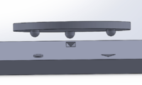
The principals of this coupling system were originally published by James Clerk Maxwell in 1871.[2] The Maxwell Kinematic system consists of three V-shaped grooves that are oriented to the center of the part, while the mating part has three curved surfaces that sit down into the three grooves.[1] Each of the three v-grooves provides two contact points for a total of six. This design benefits from symmetry and therefore easier manufacturing techniques. Also the Maxwell Coupling is thermally stable due to this symmetry as the curved surfaces can expand or contract in unison in the v-grooves.[2]
Theory
The reproducible and precision of a kinematic coupling comes from the idea of Exact Constraint Design. The principle of Exact Constrain Design is the number of points of constraint should be equal to the number of degrees of freedom to be constrained.[1] In a mechanical system there are six potential degrees of freedom. There are three linear degrees of freedom, the "x", "y", and "z" axis, and three rotational degrees of freedom around each axis commonly called pitch, roll and yaw.[2] If a system is under constrained then the two parts are free to move in one of the degrees of freedom. if the system is over constrained it can cause the system to break down under deformation, extra care needs to be taken when designing an over constrained system. Kinematic coupling designs only make contact with the number of points equal to the number of degrees of freedom that are to be restrained and therefore makes predictable.
See also
References
- 1 2 3 4 Slocum, Alexander. "Kinematic Couplings: A Review of Design Principles and Applications". MIT Open Access Articles. Elsevier B.V. Retrieved 5 October 2016.
- 1 2 3 4 Bal-tec. "The Kinematic Encyclopedia". Bal-tec. Retrieved 5 October 2016.