Instrument transformer
Instrument transformers are high accuracy class electrical devices used to isolate or transform voltage or current levels. The most common usage of instrument transformers is to operate instruments or metering from high voltage or high current circuits, safely isolating secondary control circuitry from the high voltages or currents. The primary winding of the transformer is connected to the high voltage or high current circuit, and the meter or relay is connected to the secondary circuit.
Instrument transformers may also be used as an isolation transformer so that secondary quantities may be used in phase shifting without affecting other primary connected devices.[1]
Current transformer
Current transformers (CT) are a series connected type of instrument transformer. They are designed to present negligible load to the supply being measured and have an accurate current ratio and phase relationship to enable accurate secondary connected metering.
Current transformers are often constructed by passing a single primary turn (either an insulated cable or an uninsulated bus bar) through a well-insulated toroidal core wrapped with many turns of wire. This affords easy implementation on high voltage bushings of grid transformers and other devices by installing the secondary turn core inside high-voltage bushing insulators and using the pass-through conductor as a single turn primary.

A current clamp uses a current transformer with a split core that can be easily wrapped around a conductor in a circuit. This is a common method used in portable current measuring instruments but permanent installations use more economical types of current transformer. Specially constructed wideband CTs are also used, usually with an oscilloscope, to measure high frequency waveforms or pulsed currents within pulsed power systems. One type provides an IR voltage output that is proportional to the measured current; another, called a Rogowski coil, requires an external integrator in order to provide a proportional output.
Ratio
The CT is typically described by its current ratio from primary to secondary. A 1000:5 CT will provide an output current of 5 amperes when 1000 amperes are flowing through its primary winding. Standard secondary current ratings are 5 amperes or 1 ampere, compatible with standard measuring instruments. It is used to step down current for metering purposes for the safety of the equipments as well as operator.
Burden and accuracy
Burden and accuracy are usually stated as a combined parameter due to being dependent on each other.
- Metering style CTs are designed with smaller cores and VA capacities. This causes metering CTs to saturate at lower secondary voltages saving sensitive connected metering devices from damaging large fault currents in the event of a primary electrical fault. A CT with a rating of 0.3B0.6 would indicate with up to 0.6 ohms of secondary burden the secondary current will be within a 0.3 percent error parallelogram on an accuracy diagram incorporating both phase angle and ratio errors.[2]
- Relaying CTs used for protective circuits are designed with larger cores and higher VA capacities to ensure secondary measuring devices have true representations with massive grid fault currents on primary circuits. A CT with a rating of 2.5L400 would indicate it can produce a secondary voltage to 400 volts with a secondary current of 100 amperes (20 times its rated 5 ampere rating) and still be within 2.5 amperes of true accuracy.
Care must be taken that the secondary winding of a CT is not disconnected from its low-impedance load while current flows in the primary, as this may produce a dangerously high voltage across the open secondary (especially in a relaying type CT) and could permanently affect the accuracy of the transformer.
Multi-ratio CT
The secondary winding can be single ratio or have several tap points to provide a range of ratios.
Voltage transformer or potential transformer
Voltage transformers (VT), also called potential transformers (PT), are a parallel connected type of instrument transformer. They are designed to present negligible load to the supply being measured and have an accurate voltage ratio and phase relationship to enable accurate secondary connected metering.
Ratio
The PT is typically described by its voltage ratio from primary to secondary. A 600:120 PT will provide an output voltage of 120 volts when 600 volts are impressed across its primary winding. Standard secondary voltage ratings are 120 volts and 70 volts, compatible with standard measuring instruments.
Burden and accuracy
Burden and accuracy are usually stated as a combined parameter due to being dependent on each other.
- Metering style PTs are designed with smaller cores and VA capacities than power transformers. This causes metering PTs to saturate at lower secondary voltage outputs saving sensitive connected metering devices from damaging large voltage spikes found in grid disturbances. A small PT (see nameplate in photo) with a rating of 0.3W, 0.6X would indicate with up to W load (12.5 watts[3] ) of secondary burden the secondary current will be within a 0.3 percent error parallelogram on an accuracy diagram incorporating both phase angle and ratio errors. The same technique applies for the X load (25 watts) rating except inside a 0.6% accuracy parallelogram.[4]
Markings
Some transformer winding primary (usually high-voltage) connecting wires are of many types. may be labeled as H1, H2 (sometimes H0 if it is internally designed to be grounded) and X1, X2 and sometimes an X3 tap may be present. Sometimes a second isolated winding (Y1, Y2, Y3) (and third (Z1, Z2, Z3) may also be available on the same voltage transformer. The primary may be connected phase to ground or phase to phase. The secondary is usually grounded on one terminal to avoid capacitive induction from damaging low-voltage equipment and for human safety.
Types of PTs
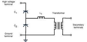
There are three primary types of potential transformers (PT): electromagnetic, capacitor, and optical. The electromagnetic potential transformer is a wire-wound transformer. The capacitor voltage transformer (CVT) uses a capacitance potential divider and is used at higher voltages due to a lower cost than an electromagnetic PT. An optical voltage transformer exploits the Faraday effect, rotating polarized light, in optical materials.[5]
References
- ↑ "Measurement Canada Standard Dwg. No.3400 D3 Delta Connected CTs" (PDF). MEASUREMENT CANADA. Retrieved 12 December 2012.
- ↑ "Limits of the 0.3 and 0.6 accuracy classes for measuring current transformers". Measurement Canada. Retrieved 18 April 2013.
- ↑ "PS-E-15 — Provisional Specifications for Approval of Electronic Voltage Transformers". Measurement Canada. Retrieved 18 April 2013.
- ↑ "PS-E-15 — Provisional Specifications for Approval of Electronic Voltage Transformers". Measurement Canada. Retrieved 18 April 2013.
- ↑ Network Protection & Automation anshu, AREVA 2002