Inertial measurement unit

An inertial measurement unit (IMU) is an electronic device that measures and reports a body's specific force, angular rate, and sometimes the magnetic field surrounding the body, using a combination of accelerometers and gyroscopes, sometimes also magnetometers. IMUs are typically used to maneuver aircraft, including unmanned aerial vehicles (UAVs), among many others, and spacecraft, including satellites and landers. Recent developments allow for the production of IMU-enabled GPS devices. An IMU allows a GPS receiver to work when GPS-signals are unavailable, such as in tunnels, inside buildings, or when electronic interference is present.[1] A wireless IMU is known as a WIMU.[2][3][4][5]
Operational principles
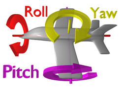
An inertial measurement unit works by detecting linear acceleration using one or more accelerometers and rotational rate using one or more gyroscopes. Some also include a magnetometer which is commonly used as a heading reference. Typical configurations contain one accelerometer, gyro, and magnetometer per axis for each of the three vehicle axes: pitch, roll and yaw.
Uses
IMUs are often incorporated into Inertial Navigation Systems which utilize the raw IMU measurements to calculate attitude, angular rates, linear velocity and position relative to a global reference frame. The IMU equipped INS forms the backbone for the navigation and control of many commercial and military vehicles such as manned aircraft, missiles, ships, submarines, and satellites. IMUs are also essential components in the guidance and control of unmanned systems such as UAVs, UGVs, and UUVs. Simpler versions of INSs termed Attitude and Heading Reference Systems utilize IMUs to calculate vehicle attitude with heading relative to magnetic north. The data collected from the IMU's sensors allows a computer to track a craft's position, using a method known as dead reckoning.
In land vehicles, an IMU can be integrated into GPS based automotive navigation systems or vehicle tracking systems, giving the system a dead reckoning capability and the ability to gather as much accurate data as possible about the vehicle's current speed, turn rate, heading, inclination and acceleration, in combination with the vehicle's wheel speed sensor output and, if available, reverse gear signal, for purposes such as better traffic collision analysis.
Besides navigational purposes, IMUs serve as orientation sensors in many consumer products. Almost all smartphones and tablets contain IMUs as orientation sensors. Fitness trackers and other wearables may also include IMUs to measure motion, such as running. IMUs also have the ability to determine developmental levels of individuals when in motion by identifying specificity and sensitivity of specific parameters associated with running. Some gaming systems such as the remote controls for the Nintendo Wii use IMUs to measure motion. Low-cost IMUs have enabled the proliferation of the consumer drone industry. They are also frequently used for sports technology (technique training),[6] and animation applications. They are a competing technology for use in motion capture technology.[7] An IMU is at the heart of the balancing technology used in the Segway Personal Transporter.
In navigation
In a navigation system, the data reported by the IMU is fed into a processor which calculates attitude, velocity and position. A typical implementation referred to as a Strap Down Inertial System integrates angular rate from the gyroscope to calculate angular position. This is fused with the gravity vector measured by the accelerometers in a Kalman filter to estimate attitude. The attitude estimate is used to transform acceleration measurements into an inertial reference frame (hence the term inertial navigation) where they are integrated once to get linear velocity, and twice to get linear position.[8][9][10]
For example, if an IMU installed in an aeroplane moving along a certain direction vector were to measure a plane's acceleration as 5 m/s2 for 1 second, then after that 1 second the guidance computer would deduce that the plane must be traveling at 5 m/s and must be 2.5 m from its initial position (assuming v0=0 and known starting position coordinates x0, y0, z0). If combined with a mechanical paper map or a digital map archive (systems whose output is generally known as a moving map display since the guidance system position output is often taken as the reference point, resulting in a moving map), the guidance system could use this method to show a pilot where the plane is located geographically in a certain moment, as with a GPS navigation system — but without the need to communicate with or receive communication from any outside components, such as satellites or land radio transponders, though external sources are still used in order to correct drift errors, and since the position update frequency allowed by inertial navigation systems can be higher the vehicle motion on the map display can be perceived as smoother. This method of navigation is called dead reckoning.
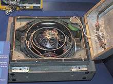
One of the earliest units was designed and built by Ford Instrument Company for the USAF to help aircraft navigate in flight without any input from outside the aircraft. Called the Ground-Position Indicator, once the pilot entered in the aircraft longitude and latitude at take off, the unit would show the pilot the longitude and latitude of the aircraft in relation to the ground.[11]
Disadvantages
A major disadvantage of using IMUs for navigation is that they typically suffer from accumulated error. Because the guidance system is continually integrating acceleration with respect to time to calculate velocity and position (see dead reckoning), any measurement errors, however small, are accumulated over time. This leads to 'drift': an ever-increasing difference between where the system thinks it is located and the actual location. Due to integration a constant error in acceleration results in a linear error in velocity and a quadratic error growth in position. A constant error in attitude rate (gyro) results in a quadratic error in velocity and a cubic error growth in position.[12]
Positional tracking systems like GPS [13] can be used to continually correct drift errors (an application of the Kalman filter).
TIMU (Timing & IMU) sensors
DARPA's Microsystems Technology Office (MTO) department is working on a Micro-PNT ("Micro-Technology for Positioning, Navigation and Timing") program to design "TIMU" ("Timing & Inertial Measurement Unit") ICs that do absolute position tracking on a single chip without GPS-aided navigation.[14][15][16]
Micro-PNT integrates a highly accurate master timing clock[17] into an IMU (Inertial Measurement Unit) chip, making it a "TIMU" ("Timing & Inertial Measurement Unit") chip. So these TIMU chips for Micro-PNT have an integrated 3-axis gyroscope, a 3-axis accelerometer, and a 3-axis magnetometer. Together with the integrated highly accurate master timing clock, it simultaneously measures the tracked movement and combines that with timing from the synchronized clock. With sensor fusion, it does absolute position tracking, all without external transmitters or transceivers.[14][15]
IMU Performance
A very wide variety of IMUs exists, depending on application types, with performance ranging:[18]
- from #0.1°/s to #0.001°/h for gyroscope
- from #100 mg to #10 µg for accelerometers.
Sensors errors
Gyroscope and accelerometer sensors behavior is often represented via a model based on the following errors, assuming they have the proper measurement range and bandwidth:
- offset error: this error can be split between stability performance (drift while the sensor remains in invariant conditions), and repeatability (error between two measurements in similar conditions separated by varied conditions in between)
- scale factor error: errors on first order sensitivity due to non repeatabilities and non linearities
- misalignment error: due to imperfect mechanical mounting
- cross axis sensitivity: parasitic measurement induced by solicitation along an axis orthogonal to sensor axis
- noise: dependent on desired dynamic performance
- environment sensitivity: mainly sensitivity to thermal gradients and accelerations
All these errors depend on various physical phenomena specific to each sensor technology. Depending on the targeted applications and to be able to make the proper sensor choice, it is then very important to consider the needs regarding stability, repeatability, and environment sensitivity (mainly thermal and mechanical environments), on both short and long terms. Targeted performance for applications is most of the time better than sensors absolute performance. However, sensor performance is repeatable over the time, with more or less accuracy, and therefore can be assessed and compensated to enhance its performance. This real-time performance enhancement is based on both sensors and IMU models. Complexity for these models will then be chosen according to the needed performance, and the type of application considered. Ability to define this model is part of sensors and IMU manufacturers know-how. Sensors and IMU models are computed in factory through a dedicated calibration sequence using multi-axes turntable and climatic chamber. They can either be computed for each individual product or generic for the whole production. Calibration will typically improve sensors raw performance by at least two decades.
IMU assembly
High performance IMUs, or IMUs designed to operate under harsh conditions are very often suspended by shock absorbers. These shock absorbers are required to master three effects:
- reduce sensor errors due to mechanical environment solicitations
- protect sensors as they can be damaged by shocks or vibrations
- contain parasitic IMU movement within a limited bandwidth, where processing will be able to compensate for them.
Suspended IMUs can offer very high performance, even when submitted to harsh environments. However, to reach such performance, it is necessary to compensate for three main resulting behaviors:
- coning: is a parasitic effect induced by two orthogonal rotations
- sculling: is a parasitic effect induced by an acceleration orthogonal to a rotation
- centrifugal accelerations effects.
Decreasing these errors tends to push IMU designers to increase processing frequencies, which becomes easier using recent digital technologies. However developing algorithms able to cancel these errors requires deep inertial knowledge and strong intimacy with sensors/IMU design. On the other side, if suspension is likely to enable IMU performance increase, it has a side effect on size and mass.
See also
- Attitude control
- Dead reckoning
- Fibre optic gyroscope
- Genesis of the Litton Inertial Navigation System
- Guidance systems
- Hemispherical resonator gyroscope
- Inertial navigation system
- Kalman filter
- LN-3 Inertial Navigation System
- MHD sensor (Magneto Hydro Dynamic sensors)
- PIGA accelerometer
- Rate integrating gyroscope
- Schuler tuning
- Spacecraft
- Vibrating structure gyroscope
References
- ↑ 'GPS system with IMUs tracks first responders'
- ↑ http://www.patentstorm.us/patents/5067084/description.html Description of IMU aiding from Roll isolated Gyro
- ↑ Inertial Navigation: 40 Years of Evolution - Overview at http://www.imar-navigation.de www.imar-navigation.de
- ↑ http://www.mathworks.com/access/helpdesk/help/toolbox/aeroblks/index.html?/access/helpdesk/help/toolbox/aeroblks/threeaxisinertialmeasurementunit.html Three Axis IMU
- ↑ http://www.starlino.com/imu_guide.html A Guide To using IMU (Accelerometer and Gyroscope Devices) in Embedded Applications
- ↑ "'An IMU-based Sensor Network to Continuously Monitor Rowing Technique on the Water'". ethz.ch.
- ↑ "The fascination for motion capture - Xsens 3D motion tracking". xsens.com.
- ↑ "OpenShoe". www.openshoe.org. Retrieved 2018-04-04.
- ↑ "GT Silicon Pvt Ltd". www.gt-silicon.com. Retrieved 2018-04-04.
- ↑ Nilsson, J. O.; Gupta, A. K.; Händel, P. (October 2014). "Foot-mounted inertial navigation made easy". 2014 International Conference on Indoor Positioning and Indoor Navigation (IPIN): 24–29. doi:10.1109/IPIN.2014.7275464.
- ↑ "Robot Navigator Guides Jet Pilots." Popular Mechanics, May 1954, p. 87.
- ↑ Siciliano, Bruno; Khatib, Oussama (20 May 2008). "Springer Handbook of Robotics". Springer Science & Business Media – via Google Books.
- ↑ IV, Hyatt Moore. "Moore Stanford Research" (PDF). web.stanford.edu.
- 1 2 "Micro-Technology for Positioning, Navigation and Timing (Micro-PNT)". www.darpa.mil.
- 1 2 http://www.darpa.mil/NewsEvents/Releases/2013/04/10.aspx Extreme Miniaturization: Seven Devices, One Chip to Navigate without GPS
- ↑ "Archived copy". Archived from the original on 2013-06-30. Retrieved 2017-07-09. Microfabrication methods to help navigate a day without GPS
- ↑ http://www.darpa.mil/Our_Work/MTO/Programs/Micro-Technology_Positioning,_Navigation_and_Timing_%28Micro-PNT%29/Clocks.aspx Micro-PNT - Clocks
- ↑ "IMU, what for: performance per application infographic - Thales Group". www.thalesgroup.com.