Hydraulic drive system
A hydraulic drive system is a quasi-hydrostatic drive or transmission system that uses pressurized hydraulic fluid to power hydraulic machinery. The term hydrostatic refers to the transfer of energy from pressure differences, not from the kinetic energy of the flow.
A hydraulic drive system consists of three parts: The generator (e.g. a hydraulic pump), driven by an electric motor or a combustion engine or a windmill; valves, filters, piping etc. (to guide and control the system); and the actuator (e.g. a hydraulic motor or hydraulic cylinder) to drive the machinery.
Principle
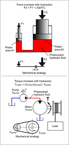
Pascal's law is the basis of hydraulic drive systems. As the pressure in the system is the same, the force that the fluid gives to the surroundings is therefore equal to pressure × area. In such a way, a small piston feels a small force and a large piston feels a large force.
The same principle applies for a hydraulic pump with a small swept volume that asks for a small torque, combined with a hydraulic motor with a large swept volume that gives a large torque. In such a way a transmission with a certain ratio can be built.
Most hydraulic drive systems make use of hydraulic cylinders. Here the same principle is used — a small torque can be transmitted into a large force.
By throttling the fluid between the generator part and the motor part, or by using hydraulic pumps and/or motors with adjustable swept volume, the ratio of the transmission can be changed easily. In case throttling is used, the efficiency of the transmission is limited. In case adjustable pumps and motors are used, the efficiency, however, is very large. In fact, up to around 1980, a hydraulic drive system had hardly any competition from other adjustable drive systems.
Currently, electric drive systems using electric servo-motors can be controlled in an excellent way and can easily compete with rotating hydraulic drive systems. Hydraulic cylinders are, in fact, without competition for linear forces. For these cylinders, if hydraulic systems are available, it is easy and logical to use this system for the rotating drives of the cooling systems.
An important advantage of a hydraulic drive is its high power density: the mass of a hydraulic drive is several times smaller than the mass of an electric drive of the same power.[1]
Classification
Hydraulic drives are traditionally divided into three classes. These are:
- Industrial hydraulics.
- Mobile hydraulics
- Aircraft hydraulics
The classification is basically due to the fact that components are classified in these categories, although some overlap exists between industrial and mobile hydraulics, aircraft hydraulics components are highly specialized due to extreme requirements on weight and certification.
Hydraulic press

A hydraulic press is a machine (see machine press) using a hydraulic cylinder to generate a compressive force. It uses the hydraulic equivalent of a mechanical lever, and was also known as a Bramah press after the inventor, Joseph Bramah, of England. He invented and was issued a patent on this press in 1795. As Bramah (who is also known for his development of the flush toilet) installed toilets, he studied the existing literature on the motion of fluids and put this knowledge into the development of the press.[2]
Hydraulic cylinder
Hydraulic cylinders (also called linear hydraulic motors) are mechanical actuators that are used to give a linear force through a linear stroke. Hydraulic cylinders are able to give pushing and pulling forces of many metric tons with only a simple hydraulic system. Very simple hydraulic cylinders are used in presses; here, the cylinder consists of a volume in a piece of iron with a plunger pushed in it and sealed with a cover. By pumping hydraulic fluid in the volume, the plunger is pushed out with a force of plunger-area pressure.
More sophisticated cylinders have a body with end cover, a piston rod, and a cylinder head. At one side the bottom is, for instance, connected to a single clevis, whereas at the other side, the piston rod is also foreseen with a single clevis. The cylinder shell normally has hydraulic connections at both sides; that is, a connection at the bottom side and a connection at the cylinder head side. If oil is pushed under the piston, the piston rod is pushed out and oil that was between the piston and the cylinder head is pushed back to the oil tank.
The pushing or pulling force of a hydraulic cylinder is as follows:
- F = Ab * pb - Ah * ph
- F = Pushing Force in N
- Ab = (π/4) * (Bottom-diameter)^2 [in m2]
- Ah = (π/4) * ((Bottom-diameter)^2-(Piston-rod-diameter)^2)) [in m2]
- pb = pressure at bottom side in [N/m2]
- ph = pressure at cylinder head side in [N/m2]
Simple hydraulic cylinders have a maximum working pressure of about 70 bar. The next step is 140 bar, 210 bar, 320/350 bar and further. In general, the cylinders are custom built. The stroke of a hydraulic cylinder is limited by the manufacturing process. The majority of hydraulic cylinders have a stroke between 0, 3, and 5 meters, whereas 12-15 meter stroke is also possible, but for this length only a limited number of suppliers are on the market.
In case the retracted length of the cylinder is too long for the cylinder to be built in the structure, Telescopic cylinder can be used. One has to realize that for simple pushing applications telescopic cylinders might be easily available; for higher forces and/or double acting cylinders, they must be designed especially and are very expensive. If hydraulic cylinders are only used for pushing and the piston rod is brought in again by other means, one can also use Plunger cylinders. Plunger cylinders have no sealing over the piston, if the piston even exists. This means that only one oil connection is necessary. In general the diameter of the plunger is rather large compared with a normal piston cylinder, whereas a hydraulic motor will always leak oil. A hydraulic cylinder does not have a leakage over the piston nor over the cylinder head sealing so that there is no need for a mechanical brake.
Hydraulic motor

The hydraulic motor is the rotary counterpart of the hydraulic cylinder. Conceptually, a hydraulic motor should be interchangeable with the hydraulic pump, due to the fact it performs the opposite function. However, most hydraulic pumps cannot be used as hydraulic motors because they cannot be backdriven. Also, a hydraulic motor is usually designed for the working pressure at both sides of the motor. Another difference is that a motor can be reversed by a reversing valve.
Pressure in a hydraulic system is like the voltage in an electrical system and fluid flow rate is the equivalent of current. The size and speed of the pump determines the flow rate, the load at the motor determines the pressure.
Hydraulic valves
These valves are usually very heavy duty to stand up to high pressures. Some special valves can control the direction of the flow of fluid and act as a control unit for a system.
Classification of hydraulic valves
- Classification based on function:
- Pressure control valves (PC Valves)
- Flow control valves (FC Valves)
- Direction control valves (DC Valves)
- Classification based on method of activation:
- Directly operated valve
- Pilot operated valve
- Manually operated valve
- Electrically actuated valve
- Open control valve
- Servo controlled valves
- manifold
Open and closed systems
An open system is one where the hydraulic fluid is returned into a large, unpressurized tank at the end of a cycle through the system. In contrast, a closed system is where the hydraulic fluid stays in one closed pressurized loop without returning to a main tank after each cycle. See open and closed systems.
See also
References
- ↑ Aranovskiy S.V.; Losenkov A.A.; Vazquez C. (2015). "Tracking control for a hydraulic drive with a pressure compensator". Scientific and Technical Journal of Information Technologies, Mechanics and Optics. 15 (4): 615–622.
- ↑ Carlisle, Rodney (2004). Scientific American Inventions and Discoveries, p. 266. John Wiley & Sons, Inc., New Jersey. ISBN 0-471-24410-4.