High-voltage transformer fire barriers
High-voltage transformer fire barriers, or transformer firewalls, transformer ballistic firewalls, transformer blast walls, are outdoor countermeasures against cascading failures in a national electric grid. The purpose of these barriers, like common fire barriers in building construction, is compartmentalisation of transformer fires, as well as transformer and bushing explosions where the fuel source of both fires and explosions is the transformer oil. Without compartmentalisation, one ruptured transformer could start its neighbouring transformer on fire and thus create a domino effect that can affect the surrounding electric grid, particularly during peak times.
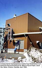
High-voltage transformer fire barriers are typically located in electrical substations, but may also be attached to buildings, such as valve halls or manufacturing plants with large electrical distribution systems, such as pulp and paper mills. Outdoor transformer fire barriers that are attached at least on one side to a building are referred to as wing walls. At times, high-voltage transformers can be located immediately outside and sometimes inside of buildings, requiring higher fire-resistance ratings[2] than other fire compartments in a building.
Substations as deliberate targets
As early as World War II, substations have been military targets. During WW2, Operation Josephine B[3] the British Special Operations Executive successfully targeted a French substation with high-voltage transformers in order to disrupt the German war effort there.
Code requirements
Outdoor structures, such as the transformers and fire barriers that separate them, do not constitute buildings, as defined by building codes. Building codes, therefore, do not typically apply to them, unless buildings are in close proximity and may be adversely affected by transformer ruptures. Where building code issues are inapplicable, no typical building permit is required, as would be the case for a house or office building[4]. If no building code applies, then also no fire code applies, as fire codes presume construction and approval per the local building code.[5] This is a crucial factor in terms of regulatory or judicial oversight concerning the construction and maintenance of transformer fire barriers.
Building construction and maintenance have the benefit of a defined Authority Having Jurisdiction[6]. When a building is designed, the architect submits drawings and specifications to the municipal or regional building department, such as the New York City Department of Buildings, along with a fee, which covers plans examinations and inspections. The building department then has a plans examiner[7] check construction documents for compliance with the applicable building code. He or she may require changes before construction may proceed. Once construction is underway, the building department typically has a building inspector checking on progress and compliance. Once a building, or occupancy, is completed and in use, the Authority Having Jurisdiction typically changes from the building department, enforcing the building code that was in effect on the date of the building permit application, over to the fire department, and, specifically the local fire prevention officer,[8] who is tasked to enforce the local fire code, which is based upon the building code. A fire prevention officer is actually a law enforcement official, who can criminally charge violators of the fire code, such as home owners or office building or plant owners. While North American outdoor transformer fire barriers use identical fire test standards to qualify fire barriers as are used in buildings (ASTM E119,[9] UL263,[10] CAN/ULC-S101,[11] and, formerly, NFPA 251[12]), and despite the fact that the national electric grid is considered critical national infrastructure,[13] there is no governmental oversight, such as exists for any buildings. For example, in buildings, it is customary to have to prove compliance with codes by means of certification listings, bounding and certification marks. This is the easiest way to communicate to an Authority Having Jurisdiction, that the item tested is identical to the item being sold and installed as intended and within the tolerances indicated in the certification listing, which summarises the test report. However, in the absence of a code for such outdoor installations, as is the case in North America, there is also no AHJ to make sure that what is being installed is verified by a third party to be fit for purpose, which leaves the property owners to perform this task. In the absence of certification listings that bound the installed configuration, complete with certification marks on the installed fire barrier, which points to the listing number, the end-user must also interpret the test report to resolve bounding issues, which requires knowledge and comprehension of test standards, and the corresponding conditions of acceptance, as well as the raw data provided by the vendor to prove compliance. Personnel familiar with electrical matters, such as high-voltage direct current, electric power transmission and transformers, who may be expected to decide on a tender for transformer fire barriers, can thus benefit from training concerning fire-resistance ratings and fire testing, which are completely different fields, that do not ordinarily cross over into the electrical realm, particularly for outdoor installations[14] [15].
Voluntary requirements by NFPA 850
The primary North American document that deals with outdoor high-voltage transformer fire barriers is NFPA 850[16]. NFPA 850 – 2015 indicates 3.3.24.2 Fire Resistance Rating. The time, in minutes or hours, that materials or assemblies have withstood a fire exposure as determined by the tests, or methodology based on testing, as mandated in NFPA 5000[17]. NFPA 5000 states under 8.2.1.1, that the fire-resistance ratings of structural elements and building assemblies shall be determined in accordance with the prescriptive requirements of 8.2.2 based on the test procedures set forth in ASTM E 119, Standard Test Methods for Fire Tests of Building Construction and Materials, or UL 263, Standard for Fire Tests of Building Construction and Materials, or other approved test methodology or analytical methods as per §8.2.3., which refer to the use of ASCE/SFPE 29, Standard Calculation Methods for Structural Fire Protection. NFPA 850 further outlines that outdoor oil-insulated transformers should be separated from adjacent structures and from each other by firewalls, spatial separation, or other approved means for the purpose of limiting the damage and potential spread of fire from a transformer failure. 5.1.4.3 states that unless consideration of the factors in 5.1.4.2 indicates otherwise, it is recommended that any oil-insulated transformer containing 500 US gallons (1,893 L) or more of oil be separated from adjacent structures by a 2-hour–rated firewall or by spatial separation in accordance with Table 5.1.4.3. Where a firewall is provided between structures and a transformer, it should extend vertically and horizontally as indicated in Figure 5.1.4.3. 5.1.4.4 of NFPA 850 states that unless consideration of the factors in 5.1.4.2 indicates otherwise, it is recommended that adjacent oil-insulated transformers containing 500 US gallons (1,893 litres) or more of oil be separated from each other by a 2 hour–rated fire separation or by spatial separation as per Table 5.1.4.3. When the oil containment, as illustrated in Figure 5.1.4.4, consists of a large, flat concrete containment area that holds several transformers and other equipment in it without the typical pit containment areas, specific containment features to keep the oil in one transformer from migrating to any other transformer or equipment should be provided. Subsection 5.5.7 may be used for guidance. Where a firewall is provided between transformers, it should extend at least 30cm (12") above the top of the transformer casing and oil conservator tank and at least 61cm or 24" beyond the width of the transformer and cooling radiators, or to the edge of the containment area, whichever is greater. 5.1.4.5 Where a firewall is provided, it should be designed to withstand the effects of projectiles from exploding transformer bushings or lightning arresters. The above results in the following checklist for compliance against NFPA 850 and its subordinate documents (NFPA 5000, ASTM E119, UL 263, as well as NFPA 251 and CAN/ULC S101, all of which are identical, and represent the sum of North American wall fire testing standards)
Check list for compliance of transformer fire barriers with NFPA 850
| Wikimedia Commons has media related to Asymmetrical fire barriers. |
- 1.) Minimum wall fire test sample size: 100ft² or 9.3m², restrained on all four edges of the wall fire test sample restraint frame, per §8.3.1 of ASTM E119.
- 2.) Asymmetrical test samples must be tested from both sides, meaning a minimum of two identical test samples to get a fire-resistance rating, such that each of the two different sides are exposed to the same fire endurance and mandatory hose stream tests to take place within 10 minutes of the end of the fire endurance. The lowest rating or resistance achieved, of the two identical samples, is the overall rating of the wall system. Neither test sponsor, nor laboratory, get to decide beforehand which side is more or less critical or more or less likely to succeed and then only test one side. Both sides must be tested.
- 3.) Independent test laboratory: By precedent referring back to the Thermo-lag scandal indicated[18] by United States Nuclear Regulatory Commission and the Federal Register,[19] on the subject matter of claiming that the ITL Laboratory, which had fiduciary ties to Thermal Science Inc., acted as an independent laboratory, resulted in the following statement by USNRC: This is a Severity Level I violation (Supplement VII) Civil Penalty--$100,000.
- 4.)
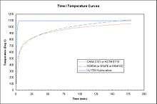 Time/Temperature curves used in North America and Europe. The UL1709 curve is also used internationally, particularly to qualify fireproofing systems for oil refineries and offshore platforms, due to the faster heat rise when burning oil, whereas ASTM E119, ISO 834,[20] DIN 4102 and BS476 are based on burning timber and thus form the basis of fire testing for buildings.
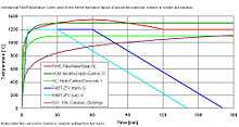 Comparison of French hydrocarbon and other curves used inside of tunnels. Still the internationally most cited time/temperature curve for hydrocarbon applications is UL 1709, which reaches ca. 1,100°C in minutes and then flatlines until the end of the test.
 This is a full scale wall furnace of Underwriters’ Laboratories of Canada, which is now defunct. Notice the black tubes that project into the fire test chamber, before which a wall test sample would be clamped. These black tubes are made of Inconel. It is a requirement in North American test standards for walls and floor/ceiling assemblies that the thermocouples used to collect furnace temperatures, in order to enter the test record, calculate a furnace average temperature for comparison against the stipulated time/temperature curve and its tolerance as well as to regulate the gas flow (fuel) into the fire chamber such that the heat exposure conforms to the standard being tested against.
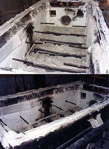 This is the now defunct ULC “4x9” medium scale fire test furnace. The Inconel tubes used to shield the furnace thermocouples are visible at mid-height. Below, one can see the gas pipes with holes to fuel the fire in accordance with the time/temperature curve, from temperature input from the shielded thermocouples. Notice the one small, black tube near the top, in the centre. This is where furnace pressure is sensed. Furnace pressure must also be regulated via calibrated equipment in order to conform to North American fire test standards.Testing shall be run in a calibrated furnace as per test standard cited, including test standard UL 1709,[21] in the event that the vendor claims to have run a hydrocarbon test. The furnace instrumentation, and, specifically, whether the furnace thermocouples are shielded, has an influence upon the severity of the initial thermal shock upon any fire test sample, whereby shielded thermocouple experience a time lag, during the first half hour of a fire test, until the heat has sufficiently soaked into the Inconel thermocouple shielding tubes, to be responsive to changes in the average furnace temperature. This means that North American furnaces can run ca. 200°C (392°F) hotter (early in the test, inflicting greater thermal shock) than European furnaces equipped with fast response thermocouples (using bare copper plates). In the aforementioned Thermo-Lag Scandal, it was determined and entered into the record of the Library of Congress in the case against Thermal Science Inc. (TSI),[22] that the ITL furnaces used to qualify Thermo-Lag circuit integrity fireproofing, were equipped with fast response thermocouples. Using a furnace equipped with fast response thermocouples, the test samples passed, but identical test samples failed when tested in accordance with the same time/temperature curve (ASTM E119 curve) when the furnace was instrumented per North American standards, using shielded thermocouples, at Omega Point Laboratories,[23] in Elmendorf, Texas, in support of the government’s case against TSI. The effect of the difference between instrumenting furnaces with shielded versus fast response thermocouples was the subject of a study by Dr. Mohamed A. Sultan of the National Research Council (Canada), with findings published in a study by Dr. Mohamed A. Sultan[24].
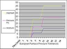 Furnace pressure is mandated by test standards to be within given tolerances, further negating the use of ad hoc outdoor testing as a means to qualify fire barriers.
 - 5.) Mandatory hose stream testing following the end of the fire endurance test within 10 minutes of gas shutoff. ASTM E119 now refers to a separate document, ASTM E2226,[25] for the hose stream test, in order to avoid duplication, as the hose stream procedure is used in other fire-resistive assemblies in addition to those tested under ASTM E119. Testing outside of North America typically excludes hose stream testing, unless witnessed by North American authorities for the purpose of obtaining ratings inside of North America. In order to qualify for a rating or to be able to use the term fire-resistance for a wall system in North America, in addition to all other requirements, there can be no through-projection of water from the exposed side to the unexposed side of the test sample.
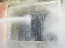 Mandatory hose stream test, of a wall system, containing a fire door. Up to and including 3 hours of fire-endurance, the pressure at the base of the nozzle is 2.1 bar or 30 PSI. From 4 hours on, the pressure must be 3.1 bars of 45PSI. The duration of the hose stream test depends on the sample size and the length of the fire endurance period: 1 minute per 100ft² (9.3m²) up to 1 hour of fire testing. 1.5 minutes per 100ft² (9.3m²) up to 1.5 hours of fire testing. 2.5 minutes per 100ft² (9.3m²) up to 3 hours of fire testing. 5 minutes per 100ft² (9.3m²) from 4 hours to less than 8 hours of fire testing. Therefore, a 6 hours fire-resistance test sample would have to undergo 45PSI (3.1 bar), at 5 minutes per 100ft² or 9.3m² in order to qualify. 6 minutes for 8 hours of fire-resistance and above per 100ft² or 9.3m².
 - 6.) The temperature on the unexposed side of the wall sample must be equipped with a minimum of 9 (nine) thermocouples, which are covered with defined ceramic fibre pads, sized 6" x 6" x 3/8" or 15 x 15 x 0.95 cm, density 18.7lbs/ft³ or 300kg/m³. The temperature rise on the unexposed side on the average of the minimum 9 thermocouples on a wall sample shall not exceed 139°C (250°F) and no single hot spot is permitted in excess of a heat rise above 181°C (325°F). The nearly identical Canadian test standard CAN/ULC-S101 (metric) states 140°C and 180°C for average, versus single point hot spot. The point in time at which either or both of those maximum heat arises, above the starting temperature before the fire has begun, is exceeded, that time period to thermal failure determines the overall rating of the assembly. Example: If a 2-hour fire endurance test, were to have a thermal failure at the 10 or 17-minute point, there would be no use in continuing the test once the limiting temperature were reached, even if the sample could, after the fire endurance period, pass the hose stream test, as any single criterion can fail the sample altogether. Temperatures radiated from a test sample to a subjective distance away from the unexposed side are immaterial, as the test standards all mandate the temperature be used that is measured by the unexposed side thermocouple, under the thermocouple pad.
Fragmentation resistance per NFPA 850 in addition to standard fire-resistance for transformer fire walls
NFPA 850 requires the following additional test criterion during a fire event:
- 5.1.4.5 Where a firewall is provided, it should be designed to withstand the effects of projectiles from exploding transformer bushings or lightning arresters.
- NFPA 850 does not provide a test procedure for this fragmentation of electrical equipment as a result of a transformer explosion. It would stand to reason that the fragmentation is a fire event, since there is no explosion without sufficient heat to ignite the transformer oil. However, added fragmentation exposures during standardised fire testing is outside of fire test standards. Therefore, the application of fragmentation following the mandatory hose stream test would leave the fire test procedure unaltered and still compliant with this requirement. Using the wording provided in NFPA 850, the test sample has to resist the effects of the fragmentation, meaning that the fragmentation should not permit the creation of see-through openings in the sample, which would during the course of a fire, permit heat and hot projectiles to traverse the barrier. What is missing, however, is data on the size, shape, momentum and number of projectiles to be employed in any qualifying tests, leaving that consideration to the end-user, particularly in the absence of a code or Authority Having Jurisdiction.
Anecdotal evidence from a transformer fire and explosion at Sinatra station,[26] on the Las Vegas strip indicates flying shrapnel, causing bodily injury[27] as well as debris being thrown onto nearby[28] Interstate 15 as well as porcelain shards[29] being embedded in a fire barrier, which would validate the NFPA 850 requirement above via anecdotal evidence.
Hydrocarbon fire testing
| Wikimedia Commons has media related to Time/Temperature Curves. |
Why test high-voltage transformer fire barriers to the hydrocarbon (UL 1709) time/temperature curve?
NFPA 850 calls for the use of the cellulosic time/temperature curve, which is over 100 years old and is based upon burning wood, as that was a predominant building material and furniture material in buildings at the time. It is a severe fire test. However, the fuel in transformer fires and explosions, is transformer oil. Oil is a hydrocarbon. Hydrocarbons burn more rapidly and release more heat faster than the same quantity of wood. Therefore, it makes sense to use standard wall fire test procedures, but to substitute a hydrocarbon time/temperature curve, because transformers are filled with oil, not wood.
Nomenclature clarification
Any reference to hydrocarbon fire testing, particularly in North America, implies the use of the UL 1709[30] time/temperature curve, which inherently also implies the use of UL1709’s provisions or furnace instrumentation. In France, and French-influenced countries, it could also mean the use of the modified French hydrocarbon curve, using fast response furnace thermocouples. Where any walls are concerned, including high-voltage transformer fire barrier walls, particularly with the use of the terms fire-resistance or fire-resistant, what is inherently implied in North America, is the use of one of the identical fire test standards that are used to evaluate non-loadbearing wall assemblies, including and limited to NFPA 251, ASTM E119, UL 263 and/or CAN/ULC-S101. European standards, such as ISO 834, DIN 4102 or BS476, that exclude the mandatory hose stream test and rely on fast response thermocouples for furnace instrumentation, cannot be implied under the terminology of “fire-resistance” or “fire-resistant” for North America, and would have to be very explicitly outlined in order to comply with the Competition Act, Section VII.1 and Title 15 of the Code of Federal Regulations, §45, which states ’’“Unfair methods of competition in or affecting commerce, and unfair or deceptive acts or practices in or affecting commerce, are hereby declared unlawful. Specifically, BS476, Part 20, 1987 makes the “insulation rating” optional (which is never the case in North American wall fire test standards), and also permits the lab’s use of depth gauges to measure maximum gaps in a fire barrier that may develop as a result of fire test exposure. Such practices are not permitted in any North American wall fire test standards. Therefore, a North American high-voltage transformer fire barrier, advertised as a hydrocarbon fire wall or hydrocarbon fire barrier, implies the use of a North American wall fire test standard, whereby the test sample is exposed to the UL 1709 time/temperature curve, substituting the cellulosic curve, using shielded thermocouples, in a calibrated furnace, and satisfying the conditions of acceptance in ASTM E119, NFPA 251, UL 263 and/or CAN/ULC S101 for non-loadbearing walls, which includes mandatory insulation and hose stream test passing performance.
Concrete used as transformer fire barrier
Cast concrete is an effective fire barrier in building construction, whose fire exposure is limited to cellulosic time/temperature curve exposures. Evidence of this is plentiful[31]. This does not mean that concrete of any mix design inherently achieves fire-resistance in all situations without careful consideration of multiple factors. For example, polypropylene fibres have been successfully used to mitigate spalling of concrete when exposed to hydrocarbon fires[32]. The types of aggregate used in concrete can affect fire resistance[33]. The amount of moisture in concrete is known to affect fire-resistance[34]. Also, typically, cementitious products and concrete slabs in fire test laboratories are equipped with moisture probes and ordinarily not subjected to fire testing unless relative humidity is at or below 75%. Further, ASTM E119 indicates in §6.2, that, prior to fire-resistance testing, test specimens are to be conditioned with the objective of providing a moisture condition within the test specimen representative of that in similar construction in buildings. For purposes of standardisation, this condition is established at equilibrium resulting from conditioning in an ambient atmosphere of 50 % relative humidity at 22.8°C or 73°F. There is public domain video evidence on concrete spalling when exposed to high temperatures[35] [36]. Both the amount of free water, which could evaporate out in hot and dry conditions, and the concentration of hydrates play a role in concrete's reaction to fire. The binder used also makes a difference, whereby calcium aluminate cements are broadly used in refractory castables. Just because a calcium aluminate cement is used in a concrete mix design, however, does not mean that there aren't important design considerations, as free water and hydrates are considered here too, to prevent spalling. In fact, it is customary for freshly placed castables to be subjected to a certain heating regime[37]in order to prevent explosive spalling as a result of heat exposure. Apart from moisture-based spalling, there is also the process of "conversion", whereby concrete made with calcium aluminate cement first gains significant strength, but then loses[38] some of it in the conversion process[39]. Incorrect use of calcium aluminate cements in construction has led to widespread problems, especially during the third quarter of the 20th century when this type of cement was used because of its faster hardening properties. The problem here was the false assumption that the pre-conversion strength was the final compression or "cold crushing" strength. After several years, some of the buildings and structures collapsed due to degradation of the cement and many had to be torn down or reinforced. Heat and humidity accelerate the conversion process; the roof of a swimming pool was one of the first structures to collapse in the UK.[40]. In Madrid, Spain, a large housing block nicknamed Korea (because it was built to house Americans during the Korean War), built 1951~1954 was affected and had to be torn down in 2006. Also in Madrid the Vicente Calderón Stadium was affected and had to be partially rebuilt and reinforced.[41]. While NFPA 850 refers to analytical methods used to determine fire-resistance of concrete structures, one must bear in mind that this refers back to building codes, which are based upon fires in relatively dry buildings. Outdoor transformer fire barrier design based on concrete, regardless whether the binder is Portland cement or calcium aluminate cement, must take into account moisture conditions both in terms of free moisture and hydrates. Simply substituting binders to refractory binders, does not eliminate the ASTM E119 requirements concerning sample conditioning. This means that one rainfall or high humidity, even with heat treatment of CAC bound concrete can affect fire-resistance. Painting the concrete does not stop steam diffusion and may just lock in moisture that can exacerbate spalling. Suppose hypothetically that a design verified an 8" or 20cm thickness of a certain concrete mix design. There is still the fire-event fragmentation to be considered as well, as its test sequencing. It is possible to overcome the technical challenges, but one must take all factors into account, or use a certification listed system, that can be verified to have taken the aforementioned factors into account.
Ballistic resistance
Utilities at times require ballistic protection of their high-voltage transformer fire barriers[42]. This can have two reasons. First, there have been a number of incidents of reports of shots fired on transformers, for example, in Nova Scotia,[43] Saskatchewan,[44] Alberta,[45] and the Metcalf sniper attack. Shooting at an operating transformer could cause a fire and explosion. This scenario could be tested by exposing the test sample to shots fired before a fire test. Secondly, since NFPA 850 mentions and anecdotal evidence confirms the possibility of fragmentation from bushings and lightning arresters, which form part of the transformer, one could argue that a ballistic test could simulate fire-event fragmentation. Both scenarios have validity, at least until NFPA adds a specific test regime or performance requirement for the fragmentation. Whether to defeat ballistic sabotage or transformer fragmentation, either the fire barrier has inherent ballistic resistance properties, or it is added on by means of armour. Vehicle armour traditionally has to consider trade-offs between resistance and weight. For a static wall, keeping the weight low is less important than for fighting vehicles, where every pound of added weight affects range and cargo carrying capacity. Also, a transformer fire barrier is not ordinarily designed to defeat artillery, whereas a main battle tank would be. However, particularly in subsequent installations, where adding the protection is an afterthought, rather than forming part of the original design, there is an incentive to keep barriers as small and modular as possible whilst defeating the given requirements of fire, fragmentation and ballistics, simply due to spatial geometry and the need to perform installation and maintenance work in confined spaces. Particularly for added armour, such as high tensile strength steel, or rolled homogeneous armour (RHA), or even combustible armour materials, such as composite material including Kevlar it is important to include such components in fire testing, as they can fundamentally alter fire-resistance performance. In the case of steel armour, this would need to be fireproofed, like all structural steel is for fire-resistant applications. If not, steel first expands and then loses its strength[46], which can cause damage. In the case of combustible materials added for ballistic resistance, meaning materials that do not pass ASTM E136,[47] these can add fuel to a fire, which is dangerous as part of a fire-resistant assembly, that should not burn from the inside or on the unexposed side, due to heat transmission and autoignition. Therefore, added ballistic resistance without being included in the qualifying fire and hose-stream testing, can have a deleterious effect, defeating the purpose of the barrier.
Ballistic testing
Internationally, there is a variety of ballistic test standards. For North America, product certification is available from the two primary fire testing and certification organisations using the ballistic test standard UL 752[48]. Those two organisations are UL LLC and Intertek. This combination of organisations that perform both fire and ballistic testing is desirable, simply because the label on the product indicates compliance. When there is no certification mark on the product installed in the field, visible upon inspection of the installed configuration, there is no third-party evidence that what is installed is identical to that which passed testing. UL752 requires ballistic testing in a calibrated range, with samples measuring 12” x 12” or 30 x 30cm, as well as the use of a calibrated gun chronograph. UL publishes such listings via Guide CNEX[49]. Intertek describes its UL752 work online,[50] as performed by its ballistic laboratory in York, Pennsylvania. Legitimate testing per UL 752 requires the use of samples conforming to the standard, sized correctly and, where necessary, tested at three different temperatures, in a calibrated range by a qualified technician. Certification mark use on the product installed in the field enables inspectors and end-users to have verification that the item tested was identical to the item being sold and used. Outdoor test samples shown in advertising, outside of the normal shot pattern, with samples outside of the parameters dictated by the test standard, particularly without the use of the certification mark, visible on the product on the installed configuration, may be indicative.
Testing sequence
Since a UL752 ballistic test sample measures 12" x 12" or 30 x 30 cm, and any legitimate wall fire-resistance test sample is minimum 100ft² or 9.3m², and since legitimate, compliant, ballistic testing must occur in a range, into which one cannot fit a full scale fire test sample, and fire test laboratories cannot, for occupational safety and health reasons, permit gunfire, testing of fire-resistance and ballistic resistance must occur on separate samples, or be out of compliance with something. For the combination between fire-resistance materials with ballistic resistance materials to be meaningful, whereby one must not defeat the other, common sense dictates that adding fire-resistive materials to a ballistic material can only improve ballistic resistance, since more material in the way of projectiles, however slight, can only improve ballistic resistance. The opposite, however, is not true. Lightweight armour using covalently bonded composite materials can add fuel to a fire. Metallic armour plating or high tensile strength steel requires fireproofing in order to retain its strength and shape. Therefore, any armour materials, both combustible and non-combustible, added to a fire-resistive assembly must be included at the time of the qualifying fire test to ASTM E119, UL263 or CAN/ULC-S101 in order to provide evidence that the complete system meets the conditions of acceptance for non-loadbearing walls. One may also, subsequently, expose 12" x 12" or 30 x 30 cm samples of the combined ballistic and fire-resistive layers in order to take advantage of the added ballistic resistance offered by the fire-resistive materials. If the fire barrier material itself were used to defeat ballistic threats and were reduced in thickness at the points of impact[51], then the overall thickness and/or configuration should be considered if the barrier must simultaneously defeat fire, fragmentation and ballistics. As an example, if a 2" or 5cm thick precast concrete panel passed a UL752 ballistic test but were reduced in thickness below the thickness necessary to achieve the mandated fire-resistance rating, then the minimum thickness of that barrier must be evaluated to simultaneously defeat all threats.
Fragmentation and ballistic testing
STANAG 4569, level 1, may be used on a full-scale wall sample in advance of fire testing, depending upon access to the test range, which may require some disassembly and re-assembly of wall modules.
Test sequencing
There are arguments for and against doing the fragmentation test before or after the fire test. It is prudent to look at all product testing to see the synergistic effects. For example, a steel-based armour plate may pass a ballistic test but may exhibit plastic deformation at the point of bullet impact. While that plate may pass the ballistic test, the plastic deformation could knock loose fire-resistive material (particularly, though not exclusively, once stressed by fire) it is in contact with and thus degrade or delete the overall system’s fire-resistance, thus defeating the point of the exercise. One of the considerations must be whether the fire-resistive barrier exhibits inherently sufficient fragmentation resistance without requiring an added layer for resisting airborne fragments or projectiles, or whether the fragmentation resistance is added on to a fire-resistive material. Either way, both must be included in fire testing, for the same reasons to do this with ballistic resistance materials, which may be one and the same, such as covalently or ionically bonded impact-resistance products. If a barrier is first exposed to fire, which has a deleterious effect, especially when combined with the mandatory hose stream testing, a metallic armour plate may have lost its strength, if it was not sufficiently fireproofed, meaning that its ballistic rating, once exposed to elevated temperatures, may be seriously degraded and will at the very least be outside of its ballistic listing bounding, which only covers temperature ranges, per UL 752, of -32°C (-25.6°F), +20°C (68°F) and + 49°C (120.2°F) (compared to fire testing, which goes up to ca. 1100°C, depending on the duration of the test). A covalently bound armour material may in fact melt and/or burn as a result of exposure in an ASTM E119 fire test, which could have a disastrous effect on a fire barrier. Combining materials, just because they can individually pass testing to one standard, does not necessarily mean that when combined with another material that has passed a different standard, that the sum of the parts will defeat testing to both standards simultaneously. The conservative approach would be to require a combined ballistic/fragmentation and fire-resistive barrier to undergo fire and hose stream testing first, and then to also defeat bullets and/or flying debris. If materials that are only individually tested, separately concerning fragmentation, ballistics, fire and hose stream, the combination would violate individual certification listings and claims or implications for such systems to meet all sets of requirements without having been tested together may be subject to interpretation in terms of the Competition Act Part VII.1, Deceptive Marketing Practices[52] and/or Title 15 of the Code of Federal Regulations §45, which states "Unfair methods of competition in or affecting commerce, and unfair or deceptive acts or practices in or affecting commerce, are hereby declared unlawful."[53]. Concerning the use of structural steel, which is identical to armour plating or high tensile strength steel, in terms of fire-resistance, it is in consideration of the reaction of unprotected steel to fire that ASTM E119 requires the instrumentation of structural steel components in fire-resistive assemblies, to determine the point in time, at which such steel components exceed a heat rise above 538°C or 1,000°F, above ambient before the fire has begun, as this has an effect upon the overall system. Consequently, the point that such temperatures upon steel have been exceeded, which is minutes into a fire test, if there is no fireproofing of the steel, be it armour or otherwise, is the point in time when loaded assemblies have failed. Such a measurement is not required for non-bearing assemblies, such as transformer fire barriers. But that does not mean that steel added on without fire testing can be done without affecting the validity of testing, let alone certification listings. For that reason, ASTM E119 states, identically to NFPA 251, UL 263 and CAN/ULC-S101, in paragraph 5.1, that the test specimen shall be representative of the construction that the test is intended to assess, as to materials, workmanship, and details such as dimensions of parts, and shall be built under conditions representative of those applied in building construction and operation. The physical properties of the materials and ingredients used in the test specimen shall be determined and recorded.
Modularity
Modularity is offered by some of the North American product vendors[54] in the realm. Modularity enables changes, for example, when one transformer ruptures, damaged wall segments can be replaced, presuming the original equipment vendor is still in business, work can proceed without complete destruction, or, if a transformer were equipped with sensors to enable a monitoring programme to judge the fitness of the transformer and/or its bushings, and the maintenance decision were to replace the transformer, then room can be made for such work by temporarily removing wall segments that are in the way during an outage. As with all such changes, similar to firestops or any passive fire protection systems, it is prudent to be able to demonstrate in advance of the qualifying fire/blast/fragmentation/ballistics testing, that initially installed segments can be demounted and then re-installed, following the manufacturer's instructions and then still pass the required qualifying tests. Typically, manufacturer's instructions accompany test reports and technicians' notes, at laboratories nationally accredited for fire testing and product certification, such as Underwriters Laboratories,[55] Intertek,[56] and Southwest Research Institute,[57][58] before public domain certification listings are issued[59]. If the intention of modularity exists in advance of the fire test, the instructions for de-mounting and re-assembly are typically followed through before the fire test, particularly if the test is intended to result in a certification listing, which results in the ability to use the laboratory's certification mark on the product, as opposed to testing for information purposes only, which does not entail assurance that the item tested is identical to the item sold and installed, in the absence of the certification label's being visible on the installed configuration as verifiable proof of compliance, pointing to the certification listing upon which the installation and local approval is based.
See also
References
- ↑ Ecmweb.com article on transformer vaults, as mentioned in NEC (National Electrical Code) or NFPA 70 Article 450: Transformers and Transformer Vaults
- ↑ Ecmweb.com article entitled "Article 450: Transformers and Transformer Vaults" by Mike Holt, dated 01. May 2008, Search for "Vault construction" Paragraph
- ↑ Afpsas.fr essay with pictures, documenting Operation Josephine B, SOE sabotage of French substation during WW2.
- ↑ City of Calgary Building and Development lists and forms, indicating need for building permits for new buildings as well as changes to existing ones
- ↑ Province of British Columbia Explanatory Guide entitled "The Codes", indicating that the BC Building Code is for new construction, whereas the BC Fie Code is for buildings that are already in use.
- ↑ Gridalternatives.org explanatory guide concerning AHJs, Authority Having Jurisdiction
- ↑ Wisegeek.com definition of "plans examiner"
- ↑ Fire prevention officer job description, City of Iroquois Falls, Ontario, Canada
- ↑ ASTM E119 Standard Test Methods for Fire Tests of Building Construction and Materials
- ↑ UL263 Standard for Fire Tests of Building Construction and Materials
- ↑ CAN/ULC-S101 Standard Methods of Fire Endurance Tests of Building Construction and Materials Fifth Edition
- ↑ NFPA 251 Standard Methods of Tests of Fire Resistance of Building Construction and Materials
- ↑ National Critical Infrastructure Security and Resilience Month: Improving the Security and Resilience of the Nation's Grid November 3, 2015 by Patricia A. Hoffman, OE-1
- ↑ Illinois Electrical & Computer Engineering Curriculum for Electrical Engineering, lacking mention of fire-resistance testing per ASTM E119, NFPA 251, NFPA 850, NFPA 5000, CAN/ULC-S101, UL 263, BS476, DIN 4102, ISO 834
- ↑ MIT EECS Curriculum page for Electrical Engineering, lacking any mention of fire-resistance testing per ASTM E119, NFPA 251, NFPA 850, NFPA 5000, CAN/ULC-S101, UL 263, BS476, DIN 4102, ISO 834
- ↑ NFPA 850 Recommended Practice for Fire Protection for Electric Generating Plants and High-Voltage Direct Current Converter Stations
- ↑ NFPA 5000 Building Construction and Safety Code®
- ↑ Thermo-Lag 330-1 Fire Barriers (Generic Letter 92-08) by United States Nuclear Regulatory Commission
- ↑ Federal Register Volume 64, Number 90 (Tuesday, May 11, 1999) Pages 25376-25383, NUCLEAR REGULATORY COMMISSION, EA 95-009, Thermal Science, Inc.; Order Imposing Civil Monetary Penalty - $900,000
- ↑ ISO 834 Fire-Resistance Tests
- ↑ UL White Paper on UL 1709 Tested Systems: "The Protection of Structural Steel in Hydrocarbon Fires"
- ↑ Bloomberg Abstract on Thermal Science Inc.
- ↑ Trademarkia.com reference to Omega Point Laboratories, which was acquired by Intertek
- ↑ Comparisons of furnace temperature and incident heat flux in wall and floor furnaces controlled by six different temperature sensors Sultan, M. A. NRCC-52644 July 2010
- ↑ ASTM E2226 Standard Practice for Application of Hose Stream
- ↑ Powereng.com article on new L3 Sinatra substation located on the Strip in Las Vegas
- ↑ Firerescue1.com article entitled: "Transformer explosion injures 2 in Las Vegas", dated 12. July 2010
- ↑ Las Vegas Sun article entitled "Transformer explosion behind Monte Carlo disrupts early morning I-15 traffic", dated Sunday, 15. May 2011, 12:52 p.m.
- ↑ Transmission Distribution World Article, re-published by intellifirewall.com, entitled "Transformer Fire Isolated" by Gordon Smith of NV Energy, dated February 2012
- ↑ Underwriters Laboratories Abstract of the Standard for Rapid Rise Fire Tests of Protection Materials for Structural Steel
- ↑ Portland Cement Association publication entitled "Fire and Concrete Structures", from "Structures 2008: Crossing Borders"
- ↑ American Concrete Institute, International Concrete Abstracts Portal, "Testing of Normal- and High-Strength Concrete Walls Subjected to Both Standard and Hydrocarbon Fires" by Tuan Ngo, Sam Fragomeni, Priyan Mendis, and Binh Ta, dated 01. May 2013
- ↑ Researchgate.net Abstract on Fire Resistance of Steel Slag Aggregates Concrete
- ↑ Researchgate.net Abstract on "FIRE SPALLING – THE MOISTURE EFFECT", dated September 2009 from Robert Jansson McNamee and Lars Bostrom
- ↑ YouTube video from Efectis Nederland, showing the underside of a concrete slab spalling within a half hour to the point of exposing rebar when testing to the RWS time/temperature curve
- ↑ YouTube Video from Propex, showing explosive spalling of concrete exposed to direct flame
- ↑ Journal of the European Ceramic Society Abstract on "Drying behavior of hydratable alumina-bonded refractory castables", Volume 24, Issue 5, May 2004, Pages 797-802, by Fábio A.Cardoso, Murilo D. M. Innocentini, Marcela F.S.Miranda, Fernando A. O. Valenzuela and Professor Victor C. Pandolfelli
- ↑ Concreteconstruction.net article entitled "Calcium Aluminate Cement Concrete, A rapid-hardening material which resists high temperatures and corrosive substances" by J. H. Fishwick, Posted on: 01. May 1982
- ↑ Oregon State University Publication entitled "Factors Influencing Conversion and Volume Stability in Calcium Aluminate Cement Systems" by Matthew Peter Adams, dated 28. May 2015
- ↑ Degradation of concrete made with calcium aluminate cement
- ↑ Unitshine.com Article entitled: "Development of Calcium Aluminate Cement and Arousing Problems" confirming construction failures as a result of the incorrect use of calcium aluminate cement.
- ↑ NERC Track 2A Physical Security Workshop indicating need for explosion and bullet resistance in transformer fire barriers
- ↑ CBC News article entitled "Shots fired at Newfoundland Power transformer cause outage" Damages caused 8,000-litre oil spill, Posted: 01. April 2014 13:23 NT, Last Updated: 01. April 2014
- ↑ Global News Article entitled: "Shooter causes power outage near Tisdale, Sask.: SaskPower", dated 30. November 2017, 15:01 hours, by David Giles, Senior Web Producer
- ↑ Canadianmanufacturing.com article entitled "Transformer damaged, turbines shut down after shots fired at Alta. wind farm" TransAlta staff discovered bullet holes in a transformer at its McBride Lake wind farm south of Calgary when responding to a remote alert; RCMP investigating, say shots were possibly fired from nearby road
- ↑ Steelforce.com.au article including reference to steel critical temperature
- ↑ ASTM Abstract on ASTM E136 Standard Test Method for Behavior of Materials in a Vertical Tube Furnace at 750°C
- ↑ UL LLC Standards Catalogue, Abstract of UL 752 Standard for Bullet-Resisting Equipment
- ↑ UL Online Certifications Directory CNEX.GuideInfo Bullet-resisting Materials
- ↑ Intertek Website describing its UL 752 work for bullet resisting equipment
- ↑ YouTube video showing successful ballistic testing of precast concrete, reducing the concrete thickness at the point of impact, passing UL 752 but requiring consideration of the remaining thickness in terms of the minimum thickness qualified to achieve the desired fire-resistance rating
- ↑ Government of Canada Justice Laws Website, 1985 Competition Act, (R.S.C., 1985, c. C-34) Part VII.1
- ↑ Cornell Law School. Legal Information Institute 15 U.S. Code § 45 - Unfair methods of competition unlawful; prevention by Commission
- ↑ Bing search using key words "transformer firewall modularity"
- ↑ UL Statement concerning its Accreditations
- ↑ Intertek Statement concerning Product Certification
- ↑ SwRI Statement of Accreditation and Certification
- ↑ SwRI Statement concerning Listing, Labeling and Follow Up Service
- ↑ UL Follow Up Service Abstract
External links
| Wikimedia Commons has media related to High-voltage transformer fire barriers. |
- YouTube videos on transformer fires and explosions
- YouTube videos on electric bushing explosions
- YouTube videos on lightning arrester explosions
- YouTube videos on STANAG 4569 testing
- National Electric Grid Security And Resilience Action Plan
- Idaho National Laboratory Grid Resilience
- ASTM Committee E05 on Fire Standards
- Concrete spalling in hydrocarbon fires
- YouTube video from Propex, showing explosive spalling of concrete as a result of brief fire exposure
- YouTube video from Efectis Nederland, showing spalling of concrete, exposing rebar within a half hour of RWS fire testing