Hall circles


Hall circles (also known as M-circles and N-circles) are a graphical tool in control theory used to obtain values of a closed-loop transfer function from the Nyquist plot (or the Nichols plot) of the associated open-loop transfer function. Hall circles have been introduced in control theory by Albert C. Hall in his thesis.[1]
Construction
Consider a closed-loop linear control system with open-loop transfer function given by transfer function and with a unit gain in the feedback loop. The closed-loop transfer function is given by .


To check the stability of T(s), it is possible to use the Nyquist stability criterion with the Nyquist plot of the open-loop transfer function G(s). Note, however, that only the Nyquist plot of G(s) does not give the actual values of T(s). To get this information from the G(s)-plane, Hall proposed to construct the locus of points in the G(s)-plane such that T(s) has constant magnitude and the also the locus of points in the G(s)-plane such that T(s) has constant phase angle.
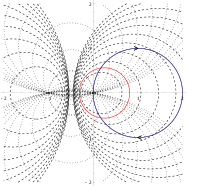
Given a positive real value M representing a fixed magnitude, and denoting G(s) by z, the points satisfying

are given by the points z in the G(s)-plane such that the ratio of the distance between z and 0 and the distance between z and -1 is equal to M. The points z satisfying this locus condition are circles of Apollonius, and this locus is known in the context of control systems as M-circles. Given a positive real value N representing a phase angle, the points satisfying
![{\displaystyle N=\arg \left[{\frac {G(s)}{1+G(s)}}\right]=\arg[G(s)]-\arg[1+G(s)]=\arg[z]-\arg[1+z]}](../I/m/3994a819a2f2e9aef0a490df8ee9ad037cf86c65.svg)
are given by the points z in the G(s)-plane such that the angle between -1 and z and the angle between 0 and z is constant. In other words, the angle opposed to the line segment between -1 and 0 must be constant. This implies that the points z satisfying this locus condition are arcs of circles,[2] and this locus is known in the context of control systems as N-circles.
Usage

To use the Hall circles, a plot of M and N circles is done over the Nyquist plot of the open-loop transfer function. The points of the intersection between these graphics give the corresponding value of the closed-loop transfer function.
Hall circles are also used with the Nichols plot and in this setting, are also known as Nichols chart. Rather than overlaying directly the Hall circles over the Nichols plot, the points of the circles are transferred to a new coordinate system where the ordinate is given by and the abscissa is given by . The advantage of using Nichols chart is that adjusting the gain of the open loop transfer function directly reflects in up and down translation of the Nichols plot in the chart.


See also
Notes
- ↑ C., Hall, Albert (1943). The analysis and synthesis of linear servomechanisms. Cambridge: Technology Press, Massachusetts Institute of Technology. ISBN 9780262080736. OCLC 857968901.
- ↑ "Munching on Inscribed Angles". cut-the-knot. Retrieved 2018-05-25.
References
- Katsuhiko, Ogata (2002). Modern control engineering (4th ed.). Upper Saddle River, NJ: Prentice Hall. ISBN 0130609072. OCLC 46619221.
- S., Nise, Norman (2008). Control systems engineering (5th ed.). Hoboken, NJ: Wiley. ISBN 9780471794752. OCLC 154798791.