Gilbert cell
In electronics, the Gilbert cell is a type of mixer. It produces output signals that are proportional to the product of two input signals. Such circuits are widely used for frequency conversion in radio systems.[1] The advantage of this circuit is the output current is an accurate multiplication of the (differential) base currents of both inputs. As a mixer, its balanced operation cancels out many unwanted mixing products, resulting in a "cleaner" output.
It is a generalized case of an early circuit first used by Howard Jones in 1963,[2] invented independently and greatly augmented by Barrie Gilbert in 1967.[3] It is actually a specific example of “translinear” design, a current-mode approach to analog circuit design. The specific property of this cell is that the differential output current is a precise algebraic product of its two, differential analog current inputs.
Function
 |
 |
 |
|---|---|---|
| Howard Jones, 1963 | Gilbert, 1968 (beta independent) | Gilbert, later (beta dependent) |
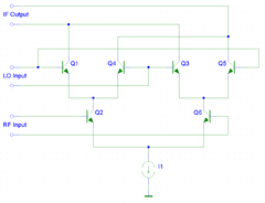
In this topology, there is little difference between the Jones cell and the translinear multiplier. In both forms, two differential amplifier stages are formed by emitter-coupled transistor pairs (Q1/Q4, Q3/Q5) whose outputs are connected (currents summed) with opposite phases. The emitter junctions of these amplifier stages are fed by the collectors of a third differential pair (Q2/Q6). The output currents of Q2/Q6 become emitter currents for the differential amplifiers. Simplified, the output current of an individual transistor is given by ic=gm vbe. Its transconductance gm is (at T=300 k) about gm=40 IC. Combining these equations gives ic=40 IC vbe,lo. However, IC here is given by vbe,rf gm,rf. Hence ic=40 vbe,lo vbe,rf gm,rf, which is a multiplication of vbe,lo and vbe,rf. Combining the two difference stages output currents yields four-quadrant operation.
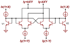
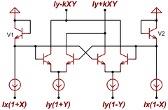
However, in the cells invented by Gilbert, shown in these figures, there are two additional diodes. This is a crucial difference, because they generate the logarithm of the associated differential (X) input current in such a way that the exponential characteristics of the following transistors result in an ideally perfect multiplication of these input currents with the remaining pair of (Y) currents. This additional diode cell topology is typically used when a low distortion VCA (Voltage Controlled Amplifier) is required. This topology is rarely used in RF mixer/modulator applications, for a variety of reasons. one being that the linearity advantage of the top linearized cascode is minimal due to the near-square wave drive signals to these bases. At very high frequencies, the drive is less likely to be a fast-edge squarewave, when there may be some advantage in the linearization.
Nowadays, functionally similar circuits can be constructed using CMOS or BiCMOS cells.
See also
- NE612, oscillator and mixer.
References
- ↑ Allen A. Sweet, Designing Bipolar Transistor Radio Frequency Integrated Circuits, Artech House, 2007, ISBN 1596931280 page 205
- ↑ Jones, Howard E., "Dual output synchronous detector utilizing transistorized differential amplifiers", U.S. patent 3,241,078A (filed: 18 June 1963 ; issued: 15 March 1966)
- ↑ Gilbert, B. (December 1968). "A precision four-quadrant multiplier with subnanosecond response". IEEE Journal of Solid-State Circuits. SC-3 (4): 353–365.