Fresnel zone
A Fresnel zone (/freɪˈnɛl/ fray-NEL), named after physicist Augustin-Jean Fresnel, is one of a series of confocal prolate ellipsoidal regions of space between and around a transmitting antenna and a receiving antenna system. The regions are used to understand and compute the strength of waves (such as sound or radio waves) propagating between a transmitter and a receiver, as well as predict whether obstructions near the line joining the transmitter and receiver will cause significant interference.
Significance
In any wave-propagated transmission between a transmitter and receiver, some amount of the radiated wave propagates off-axis (not on the line-of-sight path between transmitter and receiver). This can then reflect off of objects and then radiate to the receiver. However, the direct-path wave and the reflected-path wave may be out of phase, leading to destructive interference when the phase difference is a half-integer multiple of the period. The nth Fresnel zone is defined as the locus of points in 3D space such that a 2-segment path from the transmitter to the receiver that reflects off a point on that surface will be n half-wavelengths out of phase with the straight-line path. These will be ellipsoids with foci at the transmitter and receiver. In order to ensure limited interference, such transmission paths are designed with a certain clearance distance determined by a Fresnel-zone analysis.
The dependence on the interference on clearance is the cause of the picket-fencing effect when either the radio transmitter or receiver is moving, and the high and low signal strength zones are above and below the receiver's cut-off threshold. The extreme variations of signal strength at the receiver can cause interruptions in the communications link, or even prevent a signal from being received at all.
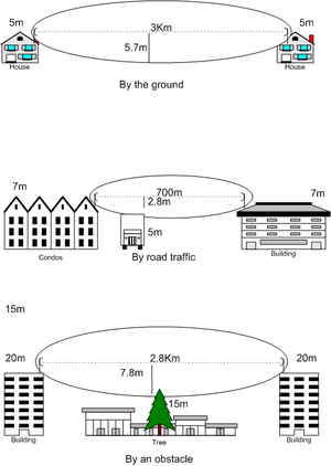
Fresnel zones are seen in optics, radio communications, electrodynamics, seismology, acoustics, gravitational radiation, and other situations involving the radiation of waves and multipath propagation. Fresnel zone computations are used to anticipate obstacle clearances required when designing highly directive systems such as microwave parabolic antenna systems. Although intuitively, line-of-sight between transmitter and receiver seems to be all that is required for a strong antenna system, because of to the complex nature of radio waves, obstructions within the first Fresnel zone can cause significant weakness, even if those obstructions are not blocking the line-of-sight signal path. For this reason, it is valuable to do a calculation of the size of the 1st, or primary, Fresnel zone for a given antenna system. Doing this will enable the antenna installer to decide if an obstacle, such as a tree, is going to make a significant impact on signal strength. The rule of thumb is that the primary Fresnel zone would ideally be 80% clear of obstacles, but must be at least 60% clear.
Spatial structure

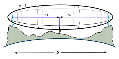
Fresnel zones are confocal prolate ellipsoidal shaped regions in space (e.g. 1, 2, 3), centered around the line of the direct transmission path (path AB on the diagram). The first region includes the ellipsoidal space which the direct line-of-sight signal passes through. If a stray component of the transmitted signal bounces off an object within this region and then arrives at the receiving antenna, the phase shift will be something less than a quarter-length wave, or less than a 90º shift (path ACB on the diagram). The effect regarding phase-shift alone will be minimal. Therefore, this bounced signal can potentially result in having a positive impact on the receiver, as it is receiving a stronger signal than it would have without the deflection, and the additional signal will potentially be mostly in-phase. However, the positive attributes of this deflection also depends on the polarization of the signal relative to the object (see the section on polarization below).
The 2nd region surrounds the 1st region but excludes the first region. If a reflective object is located in the 2nd region, the stray sine-wave which has bounced from this object and has been captured by the receiver will be shifted more than 90º but less than 270º because of the increased path length, and will potentially be received out-of-phase. Generally this is unfavorable. But again, this depends on polarization (explained below).
The 3rd region surrounds the 2nd region and deflected waves captured by the receiver will have the same effect as a wave in the 1st region. That is, the sine wave will have shifted more than 270º but less than 450º (ideally it would be a 360º shift) and will therefore arrive at the receiver with the same shift as a signal might arrive from the 1st region. A wave deflected from this region has the potential to be shifted precisely one wavelength so that it is exactly in sync with the line-of-sight wave when it arrives at the receiving antenna.
The 4th region surrounds the 3rd region and is similar to the 2nd region. And so on.
If unobstructed and in a perfect environment, radio waves will travel in a relatively straight line from the transmitter to the receiver. But if there are reflective surfaces that interact with a stray transmitted wave, such as bodies of water, smooth terrain, roof tops, sides of buildings, etc., the radio waves deflecting off those surfaces may arrive either out-of-phase or in-phase with the signals that travel directly to the receiver. Sometimes this results in the counter-intuitive finding that reducing the height of an antenna increases the signal-to-noise ratio at the receiver.
Although radio waves generally travel in a straight line, fog and even humidity can cause some of the signal in certain frequencies to scatter or bend before reaching the receiver. This means that objects that are clear of the line of sight path will still potentially block parts of the signal. To maximize signal strength, one needs to minimize the effect of obstruction loss by removing obstacles from both the direct radio frequency line of sight (RF LoS) line and also the area around it within the primary Fresnel zone. The strongest signals are on the direct line between transmitter and receiver and always lie in the first Fresnel zone.
In the early 19th century, French scientist Augustin-Jean Fresnel discovered a method to calculate where the zones are — that is, whether a given obstacle will cause mostly in-phase or mostly out-of-phase deflections between the transmitter and the receiver.
Polarization
As explained earlier, the Fresnel zone can be used to determine whether the bounced signal will be received in-phase or out-of-phase, but the transmitted polarization of a radio-frequency (RF) signal can greatly influence what actually happens at the receiving end of the transmission. Regarding polarization, an RF signal can be transmitted in different ways.
- Linear polarization — the sine wave moves on a plane
- Vertical polarization — the sine wave moves on a vertical plane
- Horizontal polarization — the sine wave moves on a horizontal plane
- Circular polarization — the sine wave moves in a tight three-dimensional helix as it leaves the transmitting antenna
- RHCP (right-hand circular polarization) — the sine wave moves clockwise as it leaves the transmitter
- LHCP (left-hand circular polarization) — the sine wave moves counter-clockwise
If a signal is vertically polarized and it deflects off a horizontal object such as a flat roof, and then bounces up to a receiving antenna, and if the roof is within the 1st region of the Fresnel zone, the resulting signal will be inverted relative to the original signal. This means the high points of the sine wave are now low points, and vice versa. Hence, even though one would expect minimal change in phase in the first Fresnel region, the bounced signal will arrive out-of-phase, which will weaken the received signal. So, the installer of the antenna system must take this into consideration and either move the transmitting antenna, receiving antenna, or both, to minimize or remove the interfering roof-deflected phase-shifted signal. Or, the installer can increase the height of either one or both the transmitting and receiving antenna so that the object (roof) that is deflecting the signal is in the 2nd region rather than the 1st (the inverted signal would behave as if it was right side up by the time it reached the receiver because of to the half-wave phase shift in region 2). Or, the installer can simply change the polarization to horizontal.
If a signal is horizontally polarized and it deflects off a horizontal object such as a flat roof, and then bounces up to a receiving antenna, and if the roof is within the 1st region of the Fresnel zone, the resulting signal will be received favorably - as it will be in-phase. The left and right extremes of the sine wave will not be negatively impacted by the deflection of the roof. In fact, this will result in a stronger signal than if there was no deflection.
For an analogy to more easily understand the differences in deflected vertically and horizontally polarized signals, place a mirror on the floor in the middle of a room. Have somebody hold a flashlight on the other side of the room. The flashlight represents a signal and your eyes are the receiver. The mirror represents a flat roof within region 1 of the Fresnel zone. Have the flashlight move up and down representing vertical polarization. Note that in the mirror, the flashlight moves in the opposite direction, that is, it moves down and up rather than up and down. This is out-of-phase. Now have the flashlight move to the left and right representing horizontal polarization. If you look in the mirror, the reflected image of the flashlight moves exactly in tandem with the actual flashlight. Left is left, right is right. This is in-phase.
If the system/signal is circular polarized, the Fresnel zone will have no effect, because a deflected circular polarized signal changes rotation upon deflection and the result is to become virtually invisible to the receiver, regardless of whether is arrives in phase or out of phase. For example, a RHCP signal that hits a street, or a wall, or anything else, then becomes a LHCP signal, and is therefore invisible to the RHCP receiving antenna, regardless of whether it arrives at the receiver in-phase or out-of-phase.
Numerous examples can be made regarding the different regions of the Fresnel zone and whether the obstacles providing bounce are sides of buildings (vertical), or streets/flat roofs (horizontal). But the same logic regarding polarization and its effects applies to the 2nd region, 3rd region, and so forth.
Fresnel zone clearance
Fresnel Zone clearance is in regards to the natural bending of waves, rather than the deflection of waves as discussed above. Atmospheric conditions such as fog can affect waves, and it's in these conditions where waves are apt to bend that Fresnel zone clearance becomes important. Although the waves are bending rather than bouncing, the impact upon the receiving antenna can be severe enough that it requires the consideration of the Fresnel Zones.
The concept of Fresnel zone clearance may be used to analyze interference by obstacles near the path of a radio beam. The first zone must be kept largely free from obstructions to avoid interfering with the radio reception. However, some obstruction of the Fresnel zones can often be tolerated. As a rule of thumb the maximum obstruction allowable is 40%, but the recommended obstruction is 20% or less.[1]
For establishing Fresnel zones, first determine the RF line of sight (RF LoS), which in simple terms is a straight line between the transmitting and receiving antennas. Now the zone surrounding the RF LoS is said to be the Fresnel zone.[2]
The general equation for calculating the Fresnel zone radius at any point P in between the endpoints of the link is the following approximate formula:

where
- is the th Fresnel zone radius,
- is the distance of P from one end,
- is the distance of P from the other end,
- is the wavelength of the transmitted signal.


The cross sectional radius of each Fresnel zone is the longest at the midpoint of the RF LoS, shrinking to a point at the antenna on each end. For practical applications, it is often useful to know the maximum radius of the first Fresnel zone. Using , , and in the above formula gives


where
- is the distance between the two antennas,
- is the frequency of the transmitted signal,
- ≈ 2.997×10⁸ m/s is the speed of light in the air.


Substitution of the numeric value for followed by a unit conversion results in an easy way to calculate the radius of the first Fresnel zone , knowing the distance between the two antennas and the frequency of the transmitted signal :

![{\displaystyle F_{1}\mathrm {[m]} =8.656{\sqrt {D\mathrm {[km]} \over f\mathrm {[GHz]} }}}](../I/m/ccf7bd68f1b0f627e590302216048c7af942b6dc.svg)
![{\displaystyle F_{1}\mathrm {[ft]} =36.03{\sqrt {D\mathrm {[mi]} \over f\mathrm {[GHz]} }}}](../I/m/3d215dd6723ea1ba4562eaafa55ff21b6755fd01.svg)
See also
References
- ↑ Coleman, Westcott, David, David (2012). Certified Wireless Network Administrator Official Study Guide. 111 River St. Hoboken, NJ 07030: John Wiley & Sons, Inc. p. 126. ISBN 978-1-118-26295-5.
- ↑ "Fresnel Zone Clearance". softwright.com. Retrieved 2008-02-21.
- ↑ Tomasi, Wayne. Electronic Communication Systems - Fundamentals Through Advanced. Pearson. p. 1023.

External links
- Online Fresnel Zone Calculator: Support the global language
- Generate 3D Fresnel zone, as a Google Earth KML file
- Fresnel zone calculator and elevation chart
- Fresnel zone calculator
- FEN Fresnel zone calculator
- More Fresnel zone details
- R.E. Sherriff, Understanding the Fresnel zone
- VHF/UHF/Microwave Radio Propagation: A Primer for Digital Experimenters