Fracture in polymers
Polymer fracture is the study of the fracture surface of an already failed material to determine the method of crack formation and extension in polymers both fiber reinforced and otherwise.[1] Failure in polymer components can occur at relatively low stress levels, far below the tensile strength because of four major reasons: long term stress or creep rupture, cyclic stresses or fatigue, the presence of structural flaws and stress-cracking agents. Formations of submicroscopic cracks in polymers under load have been studied by x ray scattering techniques and the main regularities of crack formation under different loading conditions have been analyzed. The low strength of polymers compared to theoretically predicted values are mainly due to the many microscopic imperfections found in the material. These defects namely dislocations, crystalline boundaries, amorphous interlayers and block structure can all lead to the non-uniform distribution of mechanical stress.
Long term stress or Creep Failure
Taking into account the viscoelastic path at small strain based on thermally activated rate processes. When strain attains higher values, high enough to lead to failure, its slope versus time exhibits an abrupt change. At this specific time the creep function appears a minimum.[2] In most cases DMTA (Dynamic mechanical thermal analysis) can be used to determine the viscoelastic behavior of samples as a function of time. A classic case is when the rubber hose ruptures due to creep after many years of service. DMTA can be used for o-rings and gaskets to measure the creep rates.
Fatigue Failure
The term fatigue refers to the effect of cyclic or intermittent loads. Cyclic loading due to either oscillating mechanical stress or to alternate heating and cooling, is more detrimental than static loading. Under cyclic load the crack are initialized as localized sites within the part and these extend in size during cycling. Ultimately they expand and join to such an extent that the material can no longer hold and support the stress. Fractures can be characterized by a series of concentric crack growth bands that grow from the surface initiation site. Cyclic loading can bring about failure in polymer due to: chain scission, built up heat due to hysteresis, recrystallization of material and cumulative crack generation.
Chain scission
Chain scission occurs in a polymer as a result of intense localized heat. the chemical bond in a polymer backbone may be broken with the generation of free radicles by heat, ionizing irradiation, mechanical stress and chemical reactions. These scissions multiple in number cause a fracture tip initialization to occur followed by its growth.[3]
Built-up heat from hysteresis
Polymers are viscoelastic by nature, and exhibit mechanical hysteresis even at moderate strains due to continuous elongation and contraction. Some of this inelastic deformation energy is dissipated as heat within the polymer, and consequently the materials temperature will rise as a function of frequency, testing temperature, the stress cycle and the type of polymer. As the temperature within the polymer rises, the stiffness and yield strength will fall, and thermal failure becomes a possibility as deformation levels become excessive.
Fracture Mechanics in Polymers
Fracture mechanics in polymers has become an increasingly concerning field as many industries transition to implementing polymers in many critical structural applications. As industries make the shift to implementing polymeric materials, a greater understanding of failure mechanisms for these polymers is needed . Polymers may exhibit some inherently different behaviors than metals when cracks are subject to loading. This is largely attributed to their tough and ductile mechanical properties. Microstructurally, metals contain grain boundaries, crystallographic planes and dislocations while polymers are made up of long molecular chains. In the same instance that fracture in metals involves breaking bonds, the covalent and van der Waals bonds need to be broken for fracture to occur. These secondary bonds (van der Waals) play an important role in the fracture deformation at crack tip. Many materials, such as metals, use linear elastic fracture mechanics to predict behavior at the crack tip. For some materials this is not always the appropriate way to characterize fracture behavior and an alternate model is used. Elastic-plastic fracture mechanics relates to materials that show a time independent and nonlinear behavior or in other words plastically deform. The initiation site for fracture in these materials can often occur at inorganic dust particles where the stress exceeds critical value.
Under standard linear elastic fracture mechanics, Griffiths law can be used to predict the amount of energy needed to create a new surface by balancing the amount of work needed to create new surfaces with the sample’s stored elastic energy. His popular equation below provides the necessary amount of fracture stress required as a function of crack length. E is the young’s modulus of the material, γ is the surface free energy per area and a is the crack length.

Griffith Law
While many ideas from the linear elastic fracture mechanics (LEFM) models are applicable to polymers there are certain characteristics that need to be considered when modeling behavior. Additional plastic deformation should be considered at crack tips as yielding is more likely to occur in plastics.
Yielding Mechanisms
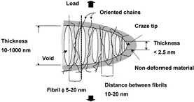
As metals yield through dislocation motions in the slip planes, polymer yield through either shear yielding or crazing.[4] In shear yielding, molecules move with respect to one another as a critical shear stress is being applied to the system resembling a plastic flow in metals. Yielding through crazing is found in glassy polymers where a tensile load is applied to a highly localized region. High concentration of stress will lead to the formation of fibrils in which molecular chains form aligned sections. This also creates voids which are known as cavitation and can be seen at a macroscopic level as a stress-whitened region as shown in Figure 1. These voids surround the aligned polymer regions.[5] The stress in the aligned fibrils will carry majority of the stress as the covalent bonds are significantly stronger than the van der Waals bonds. The plastic like behavior of polymers leads to a greater assumed plastic deformation zone in front of the crack tip altering the failure process.
Crack Tip Behavior
Just as in metals, when the stress at the crack tip approaches infinity, a yield zone will form at this crack tip front. Craze yielding is the most common yielding method at the crack front under tension due to the high triaxial stresses being applied in this local region. The Dugdale- Barenblatt strip-yield model is used to predict the length of the craze zone.[6] KI represent the stress intensity factor, s is the crazing stress being applied to the system (perpendicular to the crack in this situation), and r is the crazing zone length.

Dugdale-Barenblatt strip-yield model
The equation for stress intensity factor for a specimen with a single crack is given in the following equation where Y is a geometric parameter, s is the stress being applied and a is the crack length. For an edge crack ‘a’ is the total length of the crack where as a crack not on the edge has a crack length of ‘2a’.

Stress Intensity Equation
As the fibrils in the crack begin to rupture the crack will advance in either a stable, unstable or critical growth depending on the toughness of the material. To accurately determine the stability of a crack growth and R curve plot should be constructed. A unique tip of fracture mode is called stick/slip crack growth. This occurs when an entire crack zone ruptures at some critical crack tip opening displacement (CTOD) followed by a crack arrest and then the formation of a new crack tip.
Critical Stress Intensity Factor
The critical stress intensity factor (KIC) can be defined as the threshold value of stress intensity base on the material properties. Therefore, the crack will not propagate so long as KI is less than KIC. Since KIC is a material property it can be determined through experimental testing.[7] ASTM D20 provides a standard testing method for determining critical stress of plastics. Although KIC is material dependent it can also be a function of thickness. Where plane stress is dominant in low thickness samples increasing the critical stress intensity. As your thickness increases the critical stress intensity will decrease and eventually plateau. This behavior is caused by the transitioning from the plane stress to plain strain conditions as the thickness increases. Fracture morphology is also dependent on conditions at the located at the crack tip.
Fatigue
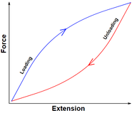
Fatigue in polymers, caused by cyclical loading, is controlled by two general methods; hysteresis heating and chain scission. If the polymer is relatively brittle it will exhibit fatigue crack growth through chain scission. In this mechanism the crack-tip yielding is limited by the brittle material properties and each loading cycle breaks a specific amount of bonds allowing the crack front to advance. Polymers with viscoelastic behavior fatigue by the hysteresis heating mechanism. In this mechanism, when loading and unloading the polymer the stress-strain curve will act as a hysteresis loop as shown in Figure 2, creating a significant amount of work on the material. This is different than an elastic material where the loading and unloading paths are the same and strain energy is able to be recovered. The work inputted into the material (area of the hysteresis loop) will be converted to heat raising the temperature of the material possibly above the glass transition temperature. This creates a localized melting at the crack tip allowing the crack to advance. The magnitude at which the crack front will advance is largely dependent on the amount/magnitude of cycles, glass transition temperature of the material and the thermal conductivity of the polymer. A polymer that has a high thermal conductivity will dissipate the heat much fast than a material with a low coefficient.
Cyclic loading of samples without a notch will be the most resistant to fatigue but can still fail based on loading conditions and cycles. A S-N curve represents the amount of cycles being applied along with the stress amplitude and can derived from the Goodman relationship.

Goodman Relationship
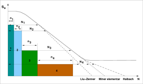
Where σf is the fatigue stress, σm is mean stress, σa is the amplitude stress and σt is the tensile stress of the sample being tested. In certain applications of polymers, materials will experience cyclic loading at different stress levels. Figure 3 gives an S-N diagram of cumulative cycles being applied at different stress amplitudes. The variable n represents the number of cycles being applied at the designated stress level and N is the fatigue life at the same stress level.

Many times, polymeric materials containing a crack are subject to cyclic loading in service. This decreases the life expectancy of the sample drastically and should be taken into consideration. In cases where polymers such as PVC follow the rules of linear elastic fracture mechanics, Paris law may be used to relate the fatigue crack propagation rate to the magnitude of stress intensity being applied. Below a certain stress intensity, crack propagation slowly increases until stable crack propagation is reached from higher levels of stress intensity. Higher levels of stress intensity leads to an unstable crack rate as shown in Figure 4. This figure is a log plot of the crack propagation rate versus the max stress intensity example. The stable crack growth regime represents the linear region of the red curve which is described using the Paris Law where ‘A’ is a pre-exponential factor.

Paris Law
Recrystallization
This process can be caused as a consequence of extensive movement of chain segments like in case or work hardening of materials.
Fatigue in Nylon
When nylon component is subjected to conditions of tensile fatigue, failure occurs when a minimum strain is reached. this means that the lifetime of nylon material is dictated by the time under load and not on the number of cycles
Fatigue of Short-Fibre-Reinforced Plastics
Fatigue failure in these reinforced polymers is due to the formation of micro cracks that are easily initiated, and which coalesce into one crack, causing the final failure [8]
Impact Fracture
A good polymer is generally defined as one capable of absorbing a large amount of energy before failure. Polycarbonates have one of the highest impact resistance values. However, amorphous polymers exhibit brittle behaviour under impact, especially if the component is notched or is too thick relative to a corner radius. The occurrence of brittle failure can be decreased by: increasing the molecular weight, inclusion of rubber phase, inducing orientation in the polymer and reducing internal defects and contaminants.
Measuring impact strength
Conventional Izod tests are used to measure the energy required to break a notched specimen. however, this is not considered as a satisfactory test. Major limitation being that most polymers as notch sensitive and fail readily under izod test.
Blends
Blended materials can have an increased fracture toughness with balanced stiffness and strength. Usually these are formed from copolymerization or modification with a suitable elastomer. However, the mechanical properties of blends, especially the modulus, follow the ‘rule of mixture’ Voigt model and the morphologies show coarsed dispersion[9]
References
- ↑ John Scheirs, “john wiley and sons”, 30-oct-2000 “[Compositional and Failure Analysis of Polymers: A Practical Approach]”
- ↑ G. Spathis, E. Kontou, “Creep failure time prediction of polymers and polymer composites”
- ↑ Robert Oboigbaotor Ebewele,"CRC Press,2000" "polymer science and technology"
- ↑ Hertzberg, Richard (2013). Deformation and Fracture Mechanics of Engineering Materials. Danvers, MA: John Wiley & Sons Inc.
- ↑ Arencon, David (November 2009). "Fracture Toughness of Polypropylene-Based Particulate Composites". Materials. 2 – via MDPI.
- ↑ Anderson, T.L. (2005). Fracture Mechanics Fundamentals and Applications Third Addition. Boca Raton, FL: Taylor and Francis Group.
- ↑ Hawinkels, R.J.H. (August 30, 2011). "Fatigue Crack Propagation in Polycarbonate". Einfhoven.
- ↑ Mandell and Lang
- ↑ Wolfgang Grellmann, Sabine Seidler, “Springer 2001” “Deformation and Fracture Behaviour of Polymers”