Floppy-disk controller
A floppy-disk controller (FDC) is a special-purpose chip and associated disk controller circuitry that directs and controls reading from and writing to a computer's floppy disk drive (FDD). This article contains concepts common to FDCs based on the NEC µPD765 and Intel 8272A or 82072A and their descendants, as used in the IBM PC and compatibles from the 1980s and 1990s. The concepts may or may not be applicable to, or illustrative of, other controllers or architectures.
Overview
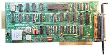
A single floppy-disk controller (FDC) board can support up to four floppy disk drives. The controller is linked to the system bus of the computer and appears as a set of I/O ports to the CPU. It is often also connected to a channel of the DMA controller. On the x86 PC the floppy controller uses IRQ 6, on other systems other interrupt schemes may be used. The floppy disk controller usually performs data transmission in direct memory access (DMA) mode.
The diagram below shows a floppy disk controller which communicates with the CPU via an Industry Standard Architecture (ISA) bus. An alternative arrangement which is more usual in recent designs has the FDC included in a super I/O chip which communicates via a Low Pin Count (LPC) bus.
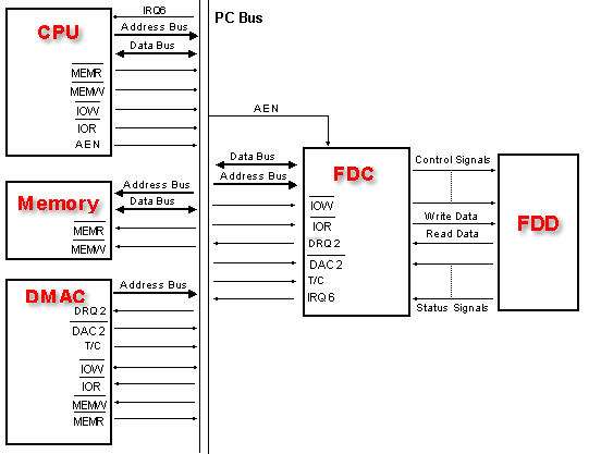
Most of the floppy disk controller (FDC) functions are performed by the integrated circuit but some are performed by external hardware circuits. The list of functions performed by each is given below.
Floppy disk controller functions (FDC)
External hardware functions
- Selection of floppy disk drive (FDD)
- Switching-on the floppy drive motor
- Reset signal for the floppy controller IC
- Enable/disable interrupt and DMA signals in the floppy disk controller (FDC)
- Data separation logic
- Write pre-compensation logic
- Line drivers for signals to the controller
- Line receivers for signals from the controller
Input/output ports for common x86-PC controller
The FDC has three I/O ports. These are:
- Data port
- Main status register (MSR)
- Digital control port
The first two reside inside the FDC IC while the Control port is in the external hardware. The addresses of these three ports are as follows.
| Port Address [hex] | Port Name | Location | Port type |
|---|---|---|---|
| 3F5 | Data port | Bidirectional I/O | |
| 3F4 | Main status register | FDC IC | Input |
| 3F2 | Digital control port | External hardware | Output |
Data port
This port is used by the software for three different purposes:
- While issuing a command to the FDC IC, command and command parameter bytes are issued to the FDC IC through this port. The FDC IC stores the different parameters and the command in its internal registers.
- After a command is executed, the FDC IC stores a set of status parameters in the internal registers. These are read by the CPU through this port. The different status bytes are presented by the FDC IC in a specific sequence.
- In the programmed and interrupt mode of data transfer, the data port is used for transferring data between the FDC IC and the CPU IN or OUT instruction.
Main status register (MSR)
This port is used by the software to read the overall status information regarding the FDC IC and the FDD's. Before initiating a floppy disk operation the software reads this port to confirm the readiness condition of the FDC and the disk drives to verify the status of the previously initiated command. The different bits of this register represent :
| Bit | Representation |
|---|---|
| 0 | FDD 0: Busy in seek mode |
| 1 | FDD 1: Busy in seek mode |
| 2 | FDD 2: Busy in seek mode |
| 3 | FDD 3: Busy in seek mode |
| 4 | FDC Busy; Read/Write command in progress |
| 5 | Non-DMA mode |
| 6 | DIO; Indicates the direction of data transfer between the FDC IC and the CPU |
| 7 | MQR; Indicates data register is ready for data transfer |
| Explanations | |
|---|---|
| MQR | 1 = data register ready, 0 = data register not ready |
| DIO | 1 = controller has data for CPU, 0 = controller expecting data from CPU |
| Non-DMA | 1 = Controller Not in DMA Mode, 0 = Controller in DMA Mode |
| FDC Busy | 1 = Busy, 0 = Not Busy |
| FDD 0,1,2,3 | 1 = Running, 0 = Not Running |
Digital control port
This port is used by the software to control certain FDD and FDC IC functions. The bit assignments of this port are:
| Bit | Representation |
|---|---|
| 0 and 1 | Device number to be selected |
| 2 | RESET FDC IC (Low) |
| 3 | Enable FDC interrupt and DMA request signals |
| 4 to 7 | Turn ON the motor in disk drive 0, 1, 2 or 3 respectively |
Format data
Many mutually incompatible floppy disk formats are possible; aside from the physical format on the disk, incompatible file systems are also possible.
| Drive | Format | Capacity | Transfer speed [kbit/s] | RPM | Tracks | TPI | Comment |
|---|---|---|---|---|---|---|---|
| 8-inch SD | 8-inch SD | 80 KB | 33.333 | 360 | 32 | 48 | Only on old controllers.[1] |
| 5.25-inch SD | 5.25-inch SD | 160 KB | 125 | 40 | Only on old controllers. | ||
| 5.25-inch SD | 5.25-inch SD | 171 KB | 250–308 | 300 | 35 | 48[2] | Only on C1541 compatibles. |
| 5.25-inch SD | 5.25-inch SD | 180 KB | 150 | 40 | Only on old controllers. | ||
| 5.25-inch DD | 5.25-inch DD | 320/360/400 KB | 250 | 300 | 40 | 48 | [3] 8/9/10 512K sectors respectively. |
| 5.25-inch DD (96 tpi) | 5.25-inch QD (2DD) | 800 KB | 250 | 300 | 80 | 96 | [4] |
| 5.25-inch HD | 5.25-inch DD | 360 KB | 300 | 360 | 40 | 48 | [5][6] |
| 5.25" HD | 5.25" HD | 1200 KB | 500 | 360 | 80 | 96 | Up to 83 tracks. Different biasing current.[5][6] |
| 5.25" HD | 5.25" HD | 720 KB | 300 | 360 | 80 | Up to 83 tracks.[3] | |
| 3.5" DD | 3.5" DD | 720 KB | 250 | 300 | 80 | 135 | Up to 83 tracks.[3][7] |
| 3.5" DD | 3.5" DD | 800 KB | 394–590 | 80 | Used by Apple Macintosh.[8] | ||
| 3.5" DD | 3.5" DD | 800 KB | 250 | 300 | 80 | Used by Commodore 1581. | |
| 3.5" DD | 3.5" DD | 880 KB | 250 | 300 | 80 | Up to 83 tracks. Used by Amiga computers. | |
| 3.5" DD | 3.5" DD | 360 KB | 250 | 300 | 40 | [3] | |
| 3.5" HD | 3.5" DD | 720 KB | 250 | 300 | 80 | Up to 83 tracks.[3] | |
| 3.5" HD | 3.5" HD | 1440 KB | 500 | 300 | 80 | 135 | Up to 83 tracks.[3][9] |
| 3.5" HD | 3.5" HD | 1760 KB | 250 | 150 | 80 | Used by Amiga computers. | |
| 3.5" ED | 3.5" ED | 2880 KB | 1000 | 300 | 80 | 135 | Up to 83 tracks.[7][10] |
Sides:
- SS (or 1S) – Single sided
- DS (or 2S) – Double sided
Density:
- SD (or 1D) – Single density (FM)
- DD (or 2D) – Double density (most often MFM)
- QD (or 4D) – Quad density
- HD – High density
- ED – Extra-high density
- TD – Triple density
"3-mode" floppy drive
Primarily in Japan there are 3.5" high-density floppy drives that support three modes of disk formats instead of the normal two – 1440 KB (2 MB unformatted), 1.2 MB (1.6 MB unformatted) and 720 kB (1 MB unformatted). Originally, the high-density mode for 3.5" floppy drives in Japan only supported a capacity of 1.2 MB instead of the 1440 KB capacity that was used elsewhere.[12] While the more common 1440 KB format spun at 300 rpm, the 1.2 MB format instead spun at 360 rpm, thereby closely resembling the 1.2 MB format with 15 sectors per track previously found on 5.25" high-density floppy drives. Later Japanese floppy drives incorporated support for both high-density formats (as well as the double-density format), hence the name 3-mode. Some BIOSes have a configuration setting to enable this mode for floppy drives supporting it.[13]
See also
- List of floppy disk formats
- Western Digital FD1771
- Integrated Woz Machine (IWM)
- Paula (Amiga controller)
References
- ↑ hypertextbook.com – Angular Speed of a Floppy Disk
- ↑ "C 64 Workshop / C= 8 Bit & Peripherals". 1998-05-19. Retrieved 2016-04-18.
- 1 2 3 4 5 6 "unifr.ch – sys/src/kernel/floppy.c". Archived from the original on 19 July 2011. Retrieved 5 May 2011.
- ↑ "Product specification single-sided and double-sided TM100 series 5 1/4-inch flexible disk drives 48, 96, and 100 tracks per inch" (PDF). Retrieved 2014-11-05.
- 1 2 iesleonardo.info – This diskette tutorial provides technical information concerning diskettes
- 1 2 oldskool.org – Let HD 5,25" FDDs operate at 300 rpm instead of 360 rpm
- 1 2 intel.com – Intel 82077SL for Super Dense Floppies Archived 8 October 2012 at the Wayback Machine.
- ↑ Johnson, Herbert R. (2016-12-22). "Floppy Drive Tech Info". Retrieved 2017-01-14.
- ↑ yi.org – High Density Floppy Disks Mf2hd Disk 3 5 1 Pk
- ↑ mcamafia.de – IBM Personal system/2, 3,5"-inch Diskette Drives, Technical Reference
- ↑ "Linux-2.6.17/drivers/block/floppy.c". 090504 gelato.unsw.edu.au
- ↑ books.google.com – Fix Your Own PC by Corey Sandler
- ↑ rojakpot.com – 3mode floppy support
- de Boyne Pollard, Jonathan (2003). "There is no such thing as a 3.5-inch floppy disc". Frequently Given Answers.
- ISO/IEC 8860-1:1987 Double-Density (DD)
- ISO/IEC 9529-1:1989 High-Density (HD)
- ISO 10994-1:1992 Extra-high-density (ED)
- ECMA-147
Further reading
- NEC µPD72070 - Floppy Disk Controller Specification Version 2.0 (PDF). 2.0 preliminary. NEC Corporation. October 1991. Archived (PDF) from the original on 2017-03-20. Retrieved 2017-03-20.
- Shah, Katen A. (1996) [September 1992, April 1992]. Intel 82077SL for Super-Dense Floppies (PDF) (Application Note) (2 ed.). Intel Corporation, IMD Marketing. AP-358, 292093-002. Archived (PDF) from the original on 2017-06-19. Retrieved 2017-06-19.