Flip Chip (PDP module)
Flip-Chip modules were used in the DEC PDP-7 (referred to in documentation as the "FLIP CHIP"), PDP-8, PDP-9 and PDP-10, beginning on August 24, 1964. The trademark "Flip-Chip"' was filed on August 27, 1964. [1] Various manuals produced by DEC refer to the modules as "FLIP CHIP", "FLIP-CHIP", "Flip Chip", and "Flip-Chip", with trademark and registered trademark symbols.
The first flip-chip modules mated with single-sided 18-contact card edge connectors with contacts on 1/8 inch centers. Circuit boards were 2 7/16 inches wide by 5 inches long, with a handle adding 1/2 inch. Double modules with two connectors end to end were 5 3/16 wide.[2] Later, when two-sided boards were introduced, compatible double-sided 36-contact edge connectors were used, but the basic board dimensions were unchanged.[3]
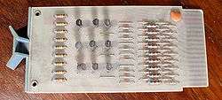
The modules were called Flip-Chips because early versions of some of these modules, for example, the R107 module shown, used hybrid integrated circuits built using flip chip mounting of individual diode chips on a ceramic substrate. Some boards containing flip chip modules were etched and drilled to allow those modules to be replaced by discrete components.[4] At some points during production, conventional discrete components may have replaced these flip-chip devices, but the early use of hybrid integrated circuits allowed DEC to market the PDP-8 as an integrated circuit computer.[5]
When DEC began to use monolithic integrated circuits, they continued to refer to their circuit boards as "Flip-Chip" modules, despite the fact that actual flip chip mounting was not used. DEC continued to hold the flip chip trademark until June 6, 1987, when the trademark was allowed to expire.[1]
References
- 1 2 "Flip Chip latest status". Retrieved 2010-05-28.
- ↑ The Digital Logic Handbook, 1966-67 edition. Maynard, Massachusetts: Digital Equipment Corporation. 1966.
- ↑ The Digital Logic Handbook, 1968 edition (PDF). Maynard, Massachusetts: Digital Equipment Corporation. 1968. p. 27.
- ↑ See, for example, the S111, component side, solder side.
- ↑ Digital Equipment Corporation, advertisement, Computers and Automation April 1965; pages 6-7.