Digital biquad filter
In signal processing, a digital biquad filter is a second-order recursive linear filter, containing two poles and two zeros. "Biquad" is an abbreviation of "biquadratic", which refers to the fact that in the Z domain, its transfer function is the ratio of two quadratic functions:

The coefficients are often normalized such that a0 = 1:

High-order IIR filters can be highly sensitive to quantization of their coefficients, and can easily become unstable. This is much less of a problem with first and second-order filters; therefore, higher-order filters are typically implemented as serially-cascaded biquad sections (and a first-order filter if necessary). The two poles of the biquad filter must be inside the unit circle for it to be stable. In general, this is true for all discrete filters i.e. all poles must be inside the unit circle in the Z-domain for the filter to be stable.
Implementation
Direct form 1
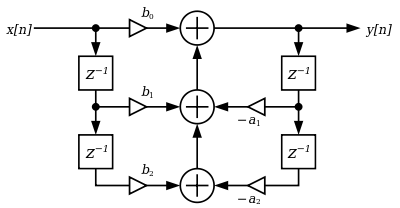
The most straightforward implementation is the direct form 1, which has the following difference equation:
![\ y[n]={\frac {1}{a_{0}}}\left(b_{0}x[n]+b_{1}x[n-1]+b_{2}x[n-2]-a_{1}y[n-1]-a_{2}y[n-2]\right)](../I/m/51d2168652d5ce30472257d7d4b94d840ba67beb.svg)
or, if normalized:
![\ y[n]=b_{0}x[n]+b_{1}x[n-1]+b_{2}x[n-2]-a_{1}y[n-1]-a_{2}y[n-2]](../I/m/dbbed7b550ce5ae4c333653731fd59815f2001fe.svg)
Here the , and coefficients determine zeros, and , determine the position of the poles.


Flow graph of biquad filter in direct form 1:
Direct form 2
The direct form 1 implementation requires four delay registers. An equivalent circuit is the direct form 2 implementation, which requires only two delay registers:
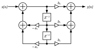
The direct form 2 implementation is called the canonical form, because it uses the minimal amount of delays, adders and multipliers, yielding in the same transfer function as the direct form 1 implementation. The difference equations for direct form 2 are:
![\ y[n]=b_{0}w[n]+b_{1}w[n-1]+b_{2}w[n-2],](../I/m/ffd7f716e1296ba7acbe9c1ffa0fe62beba53cfc.svg)
where
![\ w[n]=x[n]-a_{1}w[n-1]-a_{2}w[n-2].](../I/m/6c627a74e81ff3ff1736957f11c8337bdc37ab1a.svg)
Transposed direct forms
Each of the two direct forms may be transposed by reversing the flow graph without altering the transfer function. Branch points are changed to summers and summers are changed to branch points.[1] These provide modified implementations that accomplish the same transfer function which can be mathematically significant in a real-world implementation where precision may be lost in state storage.
The difference equations for Transposed Direct Form 2 are:
![{\displaystyle \ y[n]=b_{0}x[n]+s_{1}[n-1],}](../I/m/781206a00e173b4bb4c8633fadc817305fb5b40f.svg)
where
![{\displaystyle \ s_{1}[n]=s_{2}[n-1]+b_{1}x[n]-a_{1}y[n]}](../I/m/c3eabb9aff6fc0dd170bcb5b1cb96f79688ab09b.svg)
and
![{\displaystyle \ s_{2}[n]=b_{2}x[n]-a_{2}y[n].}](../I/m/0a7ce54b05bb366b4b1b07fc6d6a55fdf8ddd6e8.svg)
Transposed Direct form 1
The direct form 1
![]()
![]()
Transposed Direct form 2
The direct form 2
![]()
![]()
Quantizing Noise
When a sample of n bits is multiplied by a coefficient of m bits, the product has n+m bits. These products are typically accumulated in a DSP register, the addition of five products may need 3 overflow bits; this register is often large enough to hold n+m+3 bits. The z-1 is implemented by storing a value for one sample time; this storage register is usually n bits, the accumulator register is rounded to fit n bits, and this introduced quantizing noise.
In the direct form 1 arrangement, there is a single quantizing/rounding function
![]()
In the direct form 2 arrangement, there is a quantizing/rounding function for an intermediate value. In a cascade, the value may not need rounding between stages, but the final output may need rounding
![]()
Fixed point DSP usually prefers the non transposed forms and has an accumulator with a large number of bits, and is rounded when stored in main memory. Floating point DSP usually prefers the transposed form, each multiplication and potentially each addition are rounded; the additions are higher precision result, when both operands have similar magnitude.