Cottam power stations
| Cottam power station | |
|---|---|
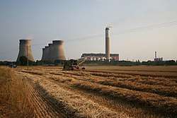 The power station, viewed from the north. July 2006. | |
| Country | England |
| Location | Cottam |
| Coordinates | 53°18′14″N 0°46′53″W / 53.304°N 0.7815°WCoordinates: 53°18′14″N 0°46′53″W / 53.304°N 0.7815°W |
| Status | Operational |
| Operator(s) |
Central Electricity Generating Board (1969-1990) Powergen (1990-2000) London Energy (2000-present) |
| Thermal power station | |
| Primary fuel | Coal |
| Secondary fuel | Oil |
| Tertiary fuel | Biomass |
| Power generation | |
| Units operational | 4 |
| Make and model | English Electric Co. Ltd. |
| Nameplate capacity | 2,000 MW |
| grid reference NZ174644 | |
The Cottam power stations are a pair of power stations. The site extends over 620 acres of mainly arable land and is situated at the eastern edge of Nottinghamshire on the west bank of the River Trent at Cottam near Retford. The larger station is coal-fired, was commissioned in 1969 by the Central Electricity Generating Board and has a generating capacity of 2,000 megawatts (MW). It is now owned by EDF Energy.[1] The smaller station is Cottam Development Centre, a combined cycle gas turbine plant commissioned in 1999, with a generating capacity of 400 MW. This plant is owned by Uniper.
The site is one of a number of power stations located along the Trent valley. The West Burton power stations are 3.5 miles (5.6 km) downstream and Ratcliffe-on-Soar power station is 52 miles (84 km) upstream. The decommissioned High Marnham Power Station was 6 miles (9.7 km) upstream. The railway to the site reopened in 1967.[2] Under the Central Electricity Generating Board in 1981/82 Cottam power station was awarded the Christopher Hinton trophy in recognition of good housekeeping the award was presented by junior Energy Minister David Mellor. After electricity privatisation in 1990, ownership moved to Powergen. In October 2000, the plant was sold to London Energy, who are part of EDF Energy, for £398 million.[3]

Construction
Work was begun in April 1964 on the site of Mickleholme Farm by the Central Electricity Generating Board Midlands Region from Bournville. The modernist architects for the buildings on site were the Nottingham practice of Yorke Rosenberg Mardall. The main contractor for the construction of the 2,000 MW power station was Balfour Beatty. The coal plant was supplied by the New Conveyor Company of Smethwick. John Thompson boilers supply steam to English Electric 500 MW steam turbines. The maximum continuous rating of each boiler is 2,400 lb/sq.in and 568 °C at the superheater. The power station opened in 1969 when owned by the Central Electricity Generating Board.
The ground level before construction varied between 3.35m and 5.18m (11 and 17 ft) ordnance datum (O.D.) In order to provide adequate protection against flooding, the area in which the main building is constructed was raised to 7.92m (26 ft) ordnance datum by filling from borrow pits on site, but the coal store and cooling tower area remain at the original level of 4.87m (16 ft) ordnance datum. The nature of the sub-soil was investigated by trial bores and found to be good load bearing marl at depths between 4.26m and 12.19m (14 and 40 ft) below the existing ground level and overlain by sand and gravel strata on top of which lay clay or silt and top soil.
The main building is 209.39m (687 ft) long by 124.35m (408 ft) wide and houses four 500 MW boiler-turbine units. The height of the boiler house is 65.22m (214 ft) and turbine house 34.44m (113 ft). The building is of steel construction with blockwork up to 10.66m (35 ft), above which there is a light-weight corrugated sheet cladding and windows.
An interesting feature of the construction of this building was the way in which the civil and steel erection work was phased. By completing the pile caps on units 1 and 2, the steel erection work was able to progress, while pile caps and flooring were completed on units 3 and 4. This enabled the steel work to be erected on units 3 and 4 from finished floor level while the flooring was being completed on units 1 and 2. This reduced the time taken to construct the main building.
Within the boiler house and between boilers 2 and 3, an escalator was erected which in several stages extended to the boiler drum level to assist with the movement of men and materials.
To the north of the main building is the precipitator bay and chimney. The four flues from the boiler are contained within a single chimney which stands 190.5m (625 ft) above ground level. In order to improve plume dispersal, the outer chimney casing is terminated 7.62m (25 ft) short of the four flues which stand at a height of 198.12m (650 ft)
To the east of the main building are eight cooling towers which are 114.3m (375 ft) in height and have a base diameter of 94.48m (310 ft) overall. Beyond this are the coal plant and the coal stocking area. The 400kV switching station is to the south of the site from which feeders join the National Grid system by way of other substations in the area. To the west are the station workshops and administration block of offices, which are connected to the turbine house by an enclosed overhead walkway. Other associated buildings such as the control block, water treatment plant house, oil storage compound etc., are disposed around and adjacent to the main building.
Considerable attention has been paid to landscaping the site in order to improve the visual appearance of the large plant. The cladding of the main building is painted in “Cottam Amber” colour, which blends perfectly with the brickwork of houses and farms in the vicinity. Extensive grassing and tree planting was carried out on land around the site when all the construction work was finished.[4]
Boilers
The four 500 MW boilers at Cottam Power Station are manufactured by John Thompson Water Tube Boilers Limited, in conjunction with Clarke Chapman & Co. Ltd. Each has an evaporation rate at M.C.R. of 1.542 tonne/hour (3,400 lb/hr). The boiler plant has been designed for short time overload operation. By by-passing two of the H.P. feed heaters and increasing the firing rate by 8% an increase of 5% electrical output can be obtained.
Coal is fed from the bunker to the fuel pulverising mills by variable speed drag-link feeders. The four barrel type mills rotated at 15 rev/min (94.25 Rad/min), and are swept by hot air which carries the P.F. mixture to eight classifiers that reject any unground pieces of coal back to the mill. Eight exhausters pass the P.F. to 32 turbulent P.F. burners arranged in four rows of eight burners on the boiler front. Each P.F. burner has an integral oil burner which is used for lighting up purposes and low load operation when instability with P.F. firing would be experienced. Combustion air is fed to the burners by two forced draught fans which pass warm air ducted from the top of the boiler house through two rotary regenerative air heaters to the secondary, or combustion air registers around each burner. The air heaters are so designed that they can be by-passed on the gas and air side to facilitate optimum operating conditions.
The boiler feed water which is passed through the economiser before entering the drum is circulated around the combustion chamber water wall tubes by any three of the four boiler water circulating pumps. Steam from the drum is passed to the H.P. turbine through a horizontal primary super heater bank, pendant super heater platens, and pendant final super heater bank. The super heater platens which are situated directly above the combustion chamber differ from other heaters in that the heat is imparted to the steam by radiation as well as convection. The other heaters being later in the gas duct rely mainly on convection for heat transfer. Steam temperature control is achieved by two stages of attemperation, one of which s between the primary super heater and the super heater platens and the other, which controls the final steam temperature, is immediately before the final super heater inlet. Exhaust steam from the H.P. turbine is returned to the boiler for re-heating at a constant pressure before being returned to the I.P. turbine. This achieved by a horizontal primary and a pendant final re-heater situated in the gas duct. Steam temperature control is achieved by non-contact type attemperators.
The boiler is kept clean by 42 gun type soot blowers in the combustion chamber and 42 long retractable blowers which clean the pendant and convection surfaces, all operating under automatic control from the control room.
The hot gasses from the combustion chamber are drawn through the super heater and re-heater banks, air heater and precipitators by induced draught fans which expel the gasses through the F.G.D. to the chimney. The fans maintain a slight vacuum within the combustion chamber in order to prevent combustion gasses leaking into the boiler house. The precipitators which are entirely of steel construction collect the dust by electrostatic means and there are no mechanical collectors.[5]
Turbo-alternators
Each of the four turbines is an English Electric Company multi-cylinder impulse reaction machine operating on a single re-heat cycle with terminal steam connections of 158.6 bar (2,300 lbf/in2), 566 degrees Celsius (1051 degrees Fahrenheit) and exhausting at a back pressure of 1.5 in Hg. Steam from the boiler passes through four strainers and two pairs of combines stop and emergency valves, each pair being associated with two throttle valves which regulate admission of steam to the H.P. cylinder inlet belt. The H.P. cylinder comprises eight stages in total. The steam expands through the first five stages towards the governor end and then re-versus its direction and flows between the inner and outer case to the last three stages. Reversing the steam flow within the H.P. cylinder helps to balance the thrust thus relieving the load on the single thrust bearing. From the H.P. cylinder the steam is fed to the boiler re-heater and returned to the I.P. cylinder through two strainers and two pairs of I.P. emergency valves, each pair of which is associated with a pair of interceptor valves which are attached to the cylinder. The I.P. section of the turbine is double flow with seven stages to each flow.
The exhaust steam from the I.P. cylinder is passed to the three L.P. cylinders by cross-over pipes reducing cross sections, which distribute the flow of steam equally to each L.P. cylinder through which it expands to the condenser. Each cylinder is double flow with five stages to each flow. A special feature of the Cottam machines is the radial condenser in which the tube nests are disposed right round the turbine L.P. shafts in a common casing. This reduces the steam velocity in the exhaust space, which together with the reduced losses in the exhaust duct improves the efficiency of the condenser. The weight of the whole structure is some hundreds of tons less than earlier structures, and the foundation block is also greatly simplified, since only a rudimentary structure above basement floor level is necessary under the L.P. turbine.[6]
Feed Water System
Following condensation of the low pressure exhaust steam in the condenser, the feed water is passed to a condensate sump mounted under the condenser. From this receiver the condensate is drawn by one or two extraction pumps and passed through a discharge strainer. The low pressure feed heating system consists of five Direct Contact heaters with one high level deaerator to provide a high feed pump suction head. The Direct Contact L.P. heaters are arranged in two banks, comprising three and two heaters respectively. Within each bank the heaters are stacked above each other so that the condensate drains from the lower pressure heater below by gravity. The heights of the heaters are approximately inversely proportional to the bled steam pressures. The advantages of Direct Contact heaters are essentially that thermal efficiency is improved, capital cost is reduced due to fewer numbers of extraction pumps being required, and the system is entirely ferrous.
The main extraction pump discharges the condensate to No.1 D.C. heater from which it cascades down to No.2 and then to No.3 D.C. heater by gravity. Two lift pumps deliver the condensate to No.4 D.C. heater, from which it cascades through No.5 D.C. heater to two deaerator lift pumps. The deaerator lift pumps discharge the condensate to the deaerator and from there it passes to the boiler feed pump suction main through microwire and magnetic filters. The main boiler feed pump is driven by a steam turbine which receives its steam from the main H.P. turbine exhaust. It comprises a single cylinder eleven stage turbine turning at 5,000 rev/min (31.42 Rad/min) and driving a multi-stage pump to give a delivery pressure of 2,067 tonne/m2 (2,940 lbf/in2). Two electrically driven Starting and Standby feed pumps are provided.
The high pressure heating system consists of two parallel banks of two heaters being numbered 7 and 8 stages in the system. Each of the H.P. heaters is vertical and of the non-contact type. From the H.P. heaters the condensate, at a temperature of 253 degrees Celsius (455 degrees Fahrenheit), is passed into the boiler economiser. During unit shutdowns the whole of the feed system can be ‘blanketed’ with nitrogen gas. This is an attempt to reduce the rate at which copper and ferrous oxides form, hence reduce the ‘carrying over’ of these oxides to the boiler drum.
Boiler feed water make-up is supplied by the Water Treatment Plant. This has a continuous rating of 3,672,000 Litres (970,000 gallons) in 24 hours at 153,300 Litres (40,500 gallons) per hour. The plant comprises three groups of cation, anion and mixed bed ion exchange resin units, together with vacuum degassing and pressure filtering plant. Each group processes 76,650 Litres (20,250 gallons) per hour and normally two groups are in service at one time, with the third on standby or being regenerated.[7]
Circulating Water System
The River Trent is tidal and navigable at the location of the station. The Trent River Board estimated the average and minimum summer flow rates to be 2,500 and 1,818 million litres per day (550 and 400 million gallons) respectively. There is no salt penetration to this reach of the river.
The total requirement for circulating water at Cottam Power Station is approximately 259.1 million Litres per hour (57 million gallons per hour), and to meet the conditions of the River Board in respect of temperature and water extraction the station is designed to work with a closed circuit cooling tower system drawing only purge and make-up water from the river. The average water requirement from the river is in the order of 113.7 million Litres per day (25 million gallons per day), of which 40.91 – 59.1 million Litres (9-13 million gallons) are required to make good evaporation losses.
The C.W. system comprises a twin culvert fed by four vertical spindle pumps feeding the condensers arranged in two parallel groups, and discharging to eight cooling towers. The cooled C.W. from the tower ponds is returned to the pump suction for re-circulation. A special feature of the C.W. plant at Cottam is the annular moat arrangement around the pump house. The moat is 45.72m (150 ft) external diameter, 5.486m (18 ft) deep and 3.048m (10 ft) wide. Suction for the four pumps is taken tangentially from the inside of the moat. This arrangement causes a continual circular, vortex free flow of water within the moat and allows any combination of the four pumps to be operated as the station demands.
To prevent formation of slime and bacterial growth automatic, intermittent dosing is provided at each condenser inlet.
The eight natural draught cooling towers each have a normal capacity of 30.69 million Litres per hour (6.75 million gallons per hour), with a normal cooling range of 8.5 degrees Celsius (47 degrees Fahrenheit). "De-icing" equipment is installed on the periphery of each tower, together with "eliminators" which reduces the system loss caused by carry over of water droplets.[8]
Coal Plant
The station consumption of coal, assuming 100% load factor, is 18,594 tonnes (18,300 tons) per day, or 5,080,235 tonnes (5,000,000 tons) per year, which used to be supplied from the nearby East Midlands Coalfields, but is now all shipped in from overseas. The site is capable of containing another station of comparable size, and in this case the coal input of the combined stations would approach 8,128,375 tonnes (8,000,000 tons) per year. The coal handling plant at the existing station is capable of extension to meet this requirement. All coal is delivered by rail over seven days of the week. Special 24.89 (24.5) and 32.51 tonne (32 ton) capacity wagons were developed with bottom hopper doors to suit the unloading equipment at this and other stations.
The maximum daily intake is in the order of 25,401 tonnes (25,000 tons) and is brought in by rail trains of approximately 1,016 tonnes (1,000 tons) pay load. The on site rail sidings form a continuous loop and wagons are unloaded whilst the train is moving at 0.8047 km/h (0.5 mph) by means of automatic line side equipment. The coal is discharged into an under ground hopper of approximately 609.6 tonnes (600 tons) capacity. Weighing of the fuel and empty wagons is carried out automatically whilst the train is moving. The time between receiving the train on site and its departure from site is less than 60 minutes.
From the under ground hopper the coal can either be fed to the bunkers in the boiler house, which have a capacity of 9,348 tonnes (9,200 tons), or to the coal stocking area. ‘Stocking Out’ is accomplished by a single radial boom conveyor feeding a working stock area of 40,642 tonnes (40,000 tons) capacity. From the working stock coal is moved by mobile plant to the permanent stock which will have a capacity of about 1,016,047 tonnes (1,000,000 tons). Reclaiming from both permanent and working stock is by mobile plant which moves the coal into and under ground hopper and hence to bunkers by means of duplicate conveyor belts, each of 1,524 tonnes (1,500 tons) per hour capacity. All operations on the coal plant, including signalling for the locomotive whilst on site, are controlled from a central room which is situated adjacent to the unloading hopper. [9]
Control Room
The station control room is situated to the east of, and adjacent to the turbine house. The control room, which is on the operating floor level, contains four separate unit control desks, together with control panels for common services such as the C.W. system, 400kV switching and works electrical system. Each unit control console comprises a semi-circular control desk, above which is an alarm facia suspended from the ceiling. Behind each control desk stands a semi-circular instrument panel. All unit operation covering start-up, loading and shut downs are carried out by the Unit Operator who sits at the control desk. The concept of the control is that all operations are divided into discreet stages, each fully automatic and self-checking, with fault alarms and light indications to show the state of the plant. The sequence for each stage is initiated by one switch on the control desk. The object of the automatic 'fixed logic' sequence control is to give consistent starting techniques which meet the matching requirements of both boiler and turbine and allows the unit to be loaded in as short a time as possible. Equipment is also provided for running up, loading and deloading the turbine as fully automated functions. Each unit has a 400 channel data logger which records instrument readings automatically and reduces the work load on the unit operator. Information recorded by the data logger is used for efficiency monitoring purposes.
Communications on the station are covered by the normal dialling telephone, and 'direct wire' telephones to important positions on the plant. Communications between control room and 'roving' operators is achieved by minaturised personal radio equipment. A 'bleeper' radio system was also used for locating staff on the station.
The site has a 24 hour security team permanently based at Cottam. Routine vehicle and foot patrols are constantly carried out. A comprehensive CCTV system is installed which enables the whole site to be comprehensively monitored around the clock.
Gas Turbines
Four 25MW gas turbine generating sets were installed in the Station, in a separate building adjacent to the 400kV switching Station. Their provision basically covered the following functions, and provided for:-
(i) An independent supply to the Station auxiliary system in time of heavy overload and low frequency on the system. Operation to meet this condition was automatic including run up, synchronising of the gas turbine and load transfer.
(ii) Peak lopping by export through the unit or Station Transformers.
(iii) Standby to the unit transformers.
(iv) Start up supplies when isolated from the grid system.
Each unit consisted of two Rolls-Royce Avon RA29 Stage 6A (1533) gas generators in parallel feeding hot gas into an English Electric Co. ltd., two stage turbine which drove a 25MW alternator. The exhaust gasses were passed into independent metal stacks, each 106.68m (350 feet) in height. The plant which was normally left un-attended could be run up to full load in a little under two minutes. The gas turbines were later decommissioned on the arrival of the new CCGT installation at Cottam Power Station.[10]
Cottam Development Centre
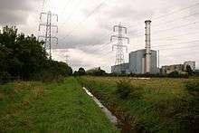
The Cottam Development Centre is a 400 MW combined cycle gas turbine (CCGT) power station, fuelled by natural gas. It was built as a joint venture between Powergen and Siemens, as a testbed for Siemens to develop CCGT technology.
Construction of the station commenced in July 1997 on a football and cricket pitch adjacent to the coal-fired power station. During construction, heavy components weighing up to 400 tonnes were brought onto site using inland waterways, to avoid damaging local roads.[11] The station opened in September 1999. In May 2002 the station was bought out by Powergen for £52 million.
Specification
The power station generates electricity using a single Siemens V94.3A (now called a SGT5-4000F) gas turbine, one BENSON heat recovery steam generator and one steam turbine.[12][13] Electricity from the station has a terminal voltage of 21 kilovolts (kV), and enters the National Grid via a transformer at 400 kV. The plant has a thermal efficiency of 58%.[11]
Industrial action
2004 Wildcat strike
Wildcat strike action was taken in December 2004, when scaffolding collapsed and injured one worker.[14]
2006 Wildcat strike
In February 2006, 51 British workers at the station walked out on Wildcat strike action due to the underpayment of Hungarian workers during construction of Flue Gas Desulphurisation equipment. The Hungarians had worse working conditions than the British workers and were underpaid £1 million by employer SFL. 15 British workers who walked out in solidarity were made redundant.[14]
References
- ↑ "Power Station Locations and Capacities". United Kingdom Quality Ash Association. Archived from the original on 25 September 2009. Retrieved 6 February 2011.
- ↑ Modern Railways September 1966 p. 506
- ↑ "Powergen generates £398m from Cottam". The Telegraph. London. 17 October 2000. Retrieved 2 August 2008.
- ↑ COTTAM. Central Electricity Generating Board MIDLANDS REGION. 1969. p. 2.
- ↑ COTTAM. Central Electricity Generating Board MIDLANDS REGION. 1969. p. 3.
- ↑ COTTAM. Central Electricity Generating Board MIDLANDS REGION. 1969. p. 2.
- ↑ COTTAM. Central Electricity Generating Board MIDLANDS REGION. 1969. p. 5.
- ↑ COTTAM. Central Electricity Generating Board MIDLANDS REGION. 1969. p. 7.
- ↑ COTTAM. Central Electricity Generating Board MIDLANDS REGION. 1969. p. 7.
- ↑ COTTAM. Central Electricity Generating Board MIDLANDS REGION. 1969. p. 9.
- 1 2 "Cottam Development Centre" (ASP). E.On UK. Retrieved 6 February 2011.
- ↑ "SGT5-4000F". Siemens. Retrieved 2 August 2008.
- ↑ "BENSON HRSG". Siemens. Retrieved 4 January 2017.
- 1 2 Steven (1 March 2006). "UK: Cottam power station wildcat strike". Retrieved 2 November 2009.
External links
| Wikimedia Commons has media related to Cottam Power Station. |
| Power stations |
|  | ||||||||||||||||||||||||||||
|---|---|---|---|---|---|---|---|---|---|---|---|---|---|---|---|---|---|---|---|---|---|---|---|---|---|---|---|---|---|---|
| Organisations | ||||||||||||||||||||||||||||||